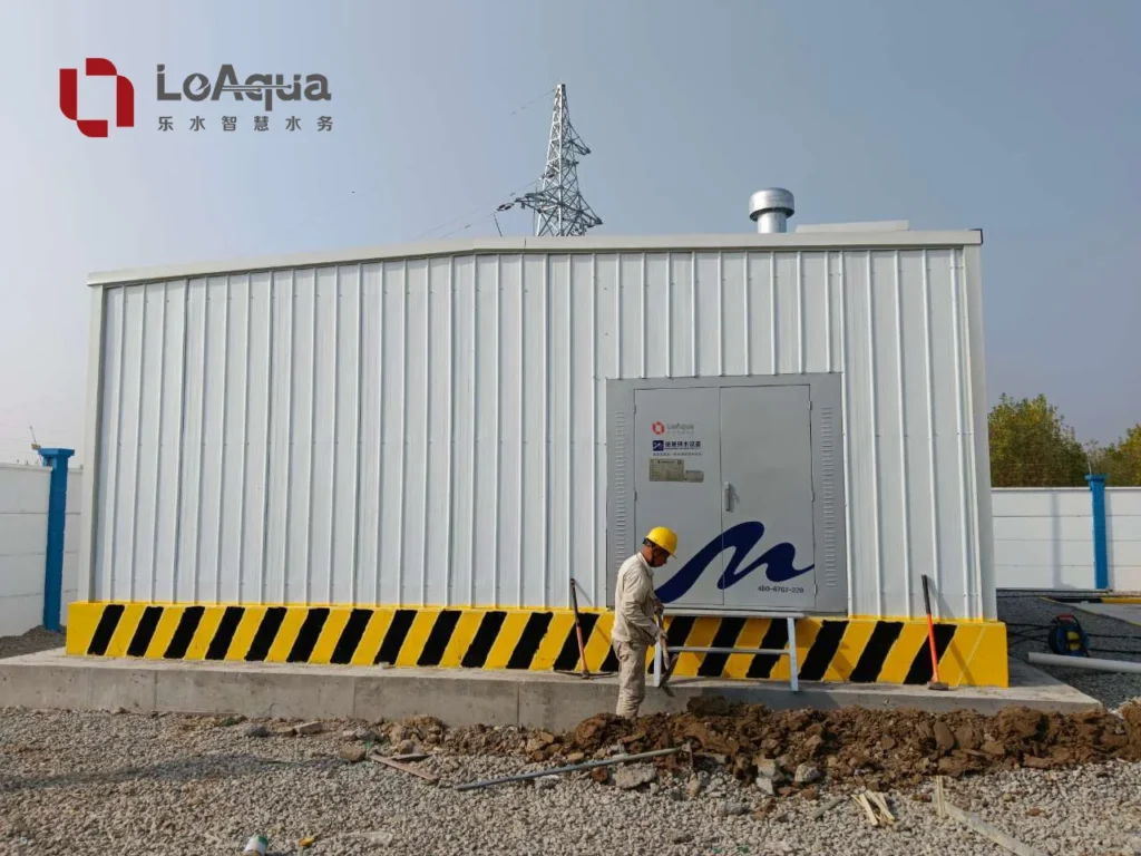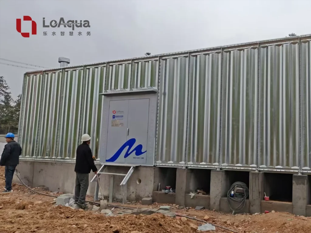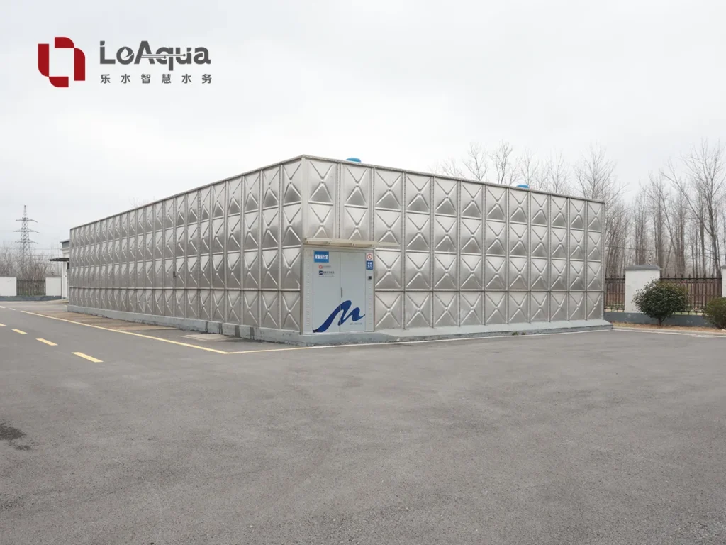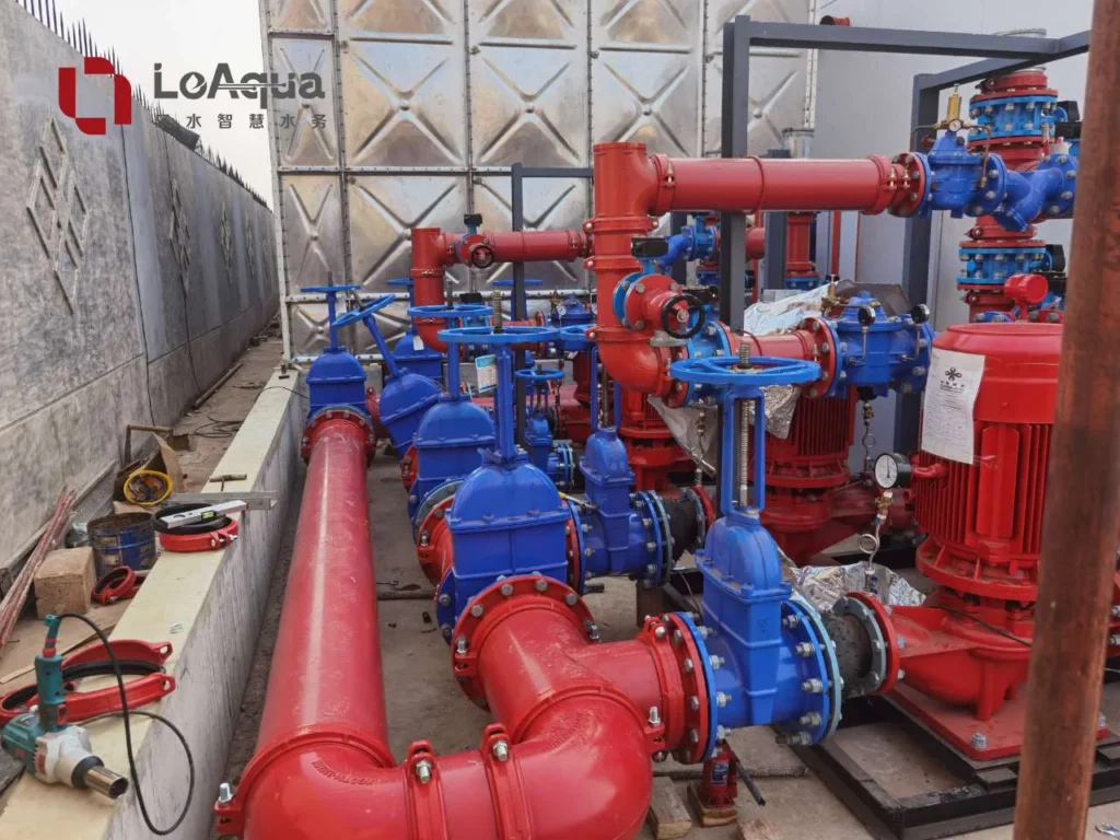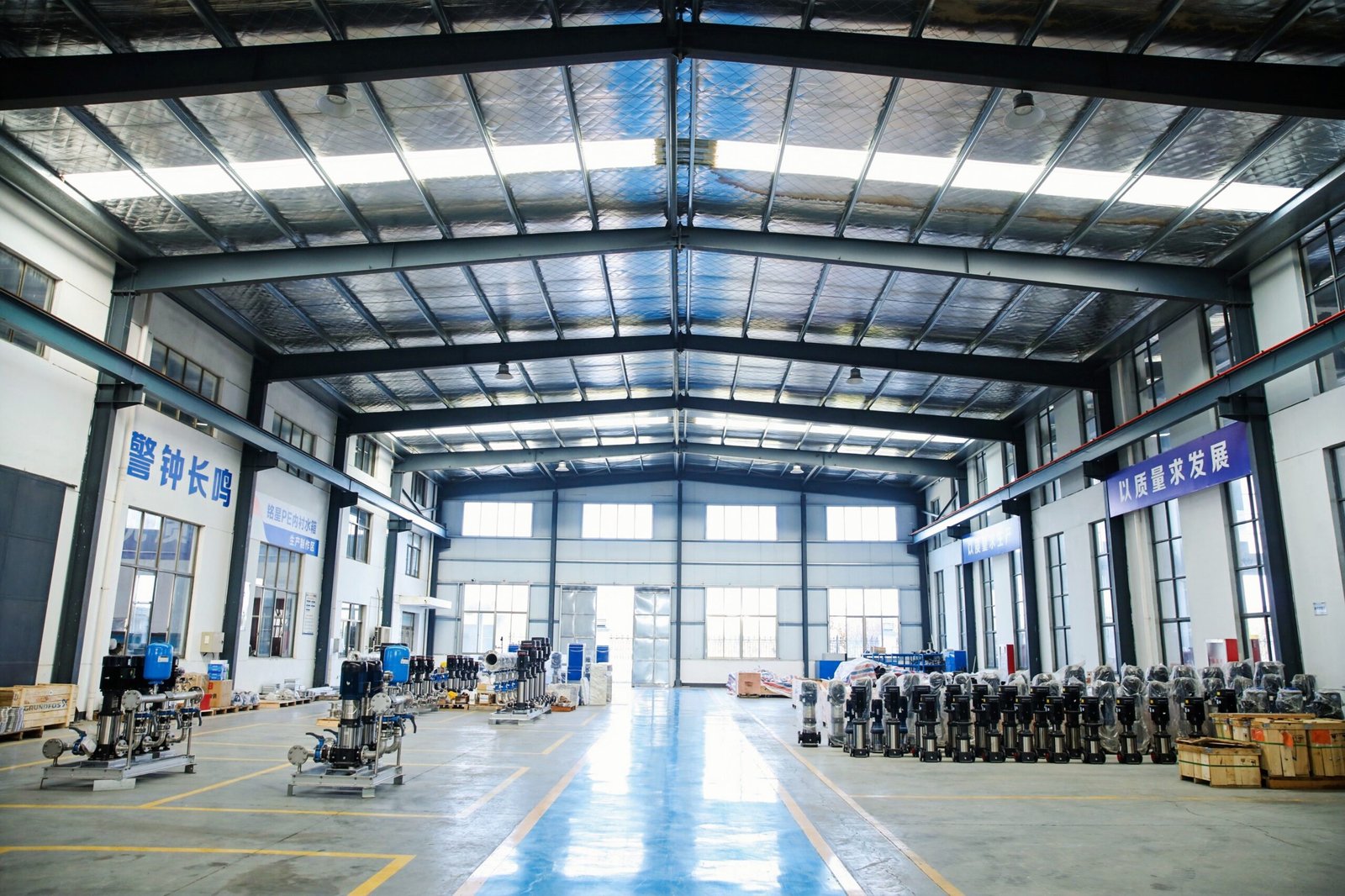
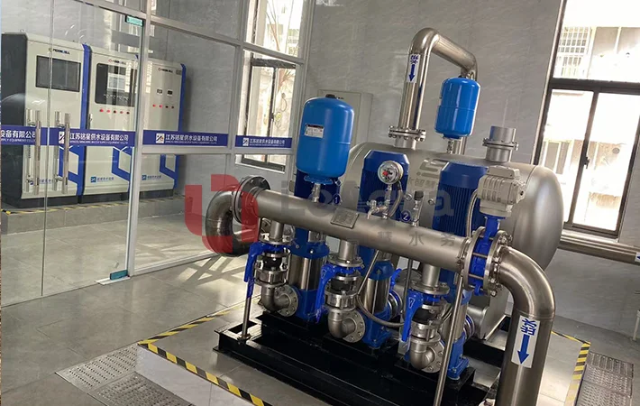
An integrated pump station is not defined by putting a pump, a water tank and a control cabinet in the same room. The engineering question is whether the selected pump can deliver the required flow and pressure under the actual suction, storage, piping and operating conditions. This is why pump selection should begin with the duty of the station, then connect the pump to the water tank, controls and maintenance plan.
This guide uses LeAqua’s integrated pump station and pump range to explain how different pump families fit different duties. For an overview of system architecture, see Integrated Pump Station Engineering: Tank, Pump and Control. It also shows why integrating the water tank at the design stage can reduce interface problems, while making clear which project responsibilities still remain on site.
What is the right pump for an integrated pump station?
The right pump is the one whose verified flow, head, fluid compatibility, installation arrangement and control method match the project duty. A pump should not be selected from the water tank capacity alone. The final choice depends on demand profile, elevation, pipe losses, required outlet pressure, water quality, solids, duty and standby requirements, power supply and maintenance access.
Why pump selection and water tank design should be connected
In a conventional procurement model, the tank, pump set, control cabinet and pipework may come from different suppliers. Each product can meet its own specification while the interfaces create problems during installation. Typical interface questions include:
- Where is the tank outlet in relation to the pump suction?
- Does the suction pipe create excessive friction loss or an unfavorable approach to the pump?
- Are the flange standards, valves, sensors and cable routes compatible?
- Is there enough space to remove a motor, inspect a split casing or clean the tank?
- Can the control system use the required pressure, level and alarm signals?
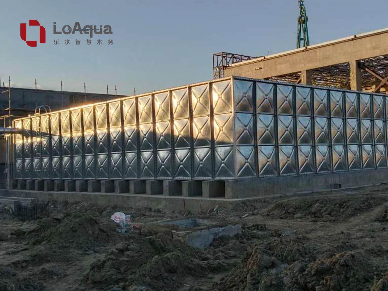
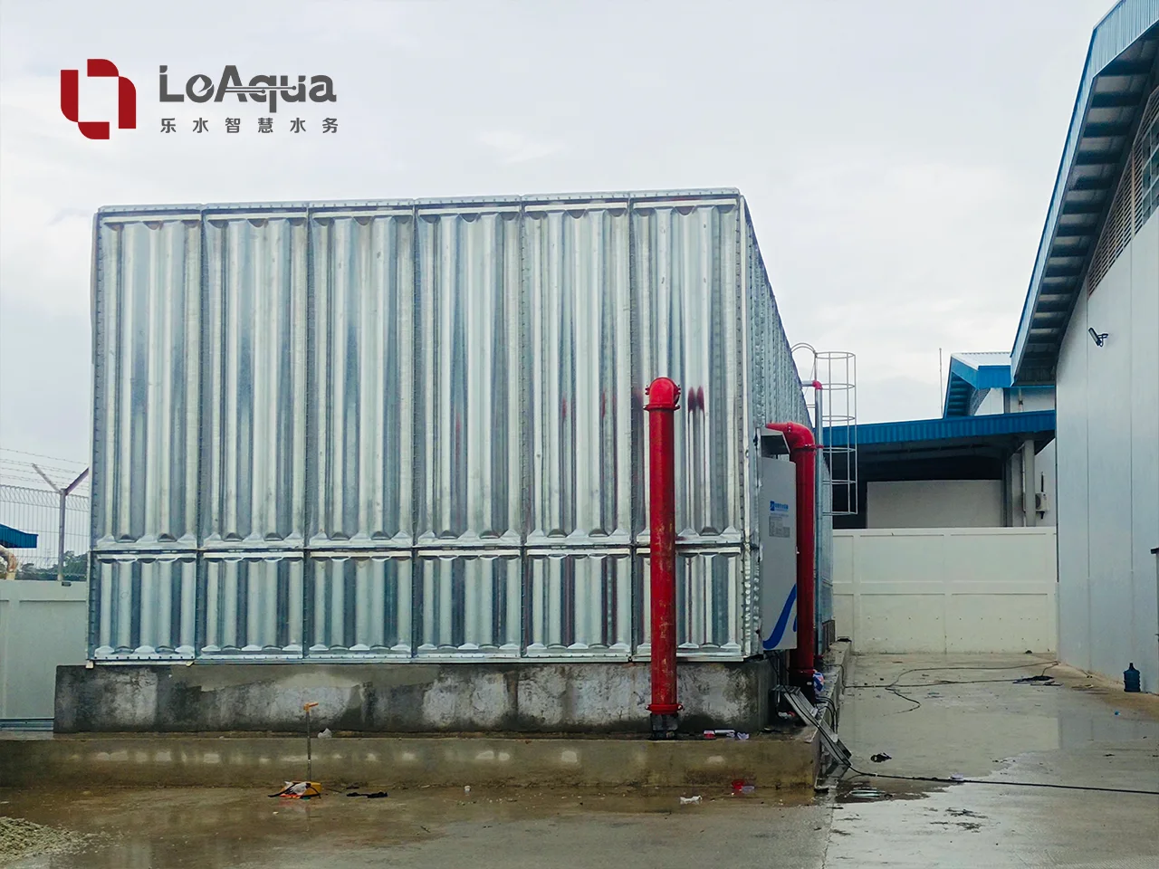
When the tank and pump station are engineered together, these interfaces can be reviewed before manufacturing. The tank becomes part of the hydraulic arrangement rather than a separate storage product. Its dimensions, outlet positions, access openings, overflow, drain, water-level control and maintenance clearances can be considered with the pump layout. With a modular arc-ribbed water tank, panel assembly and access arrangements also need to be coordinated with the pump-room layout and installation sequence.
This coordination does not remove the need for civil works, foundations, incoming power, external pipework, drainage or local approvals. It reduces the number of unknown connections that the project team has to solve after delivery.
Start with the pump station duty
Before comparing pump models, prepare a short duty statement. At minimum, it should include:
| Design input | Why it matters |
|---|---|
| Required flow | Defines how much water must be transferred or circulated in the design condition. |
| Required head or outlet pressure | Accounts for elevation, pipe friction and the pressure needed at the point of use. |
| Static elevation and pipe route | Influences the total dynamic head and suction arrangement. |
| Tank capacity and operating level | Defines available storage, water level changes and suction conditions. |
| Fluid and temperature | Determines material, seal and pump construction requirements. |
| Solids or contamination | Separates clean-water pumping from drainage, sewage or process-fluid duties. |
| Duty, standby and operating hours | Determines redundancy, sequencing and expected service conditions. |
| Power and controls | Determines motor, starter, variable-speed and monitoring requirements. |
A large water tank does not by itself identify the correct pump. The station might require a compact high-head booster, a large-flow double-suction pump, a circulation pump or a submersible sewage pump. Storage volume and pumping duty must be calculated separately and then connected through the system design.
Which pump type fits which integrated station?
How to read the ranges below: these figures are published family limits, not a selected pump’s duty point. Maximum flow and maximum head must not be assumed to occur together. Obtain the exact model’s flow–head curve, motor rating, efficiency information and suction requirements before making a selection.
1. Vertical multistage pumps for pressure boosting
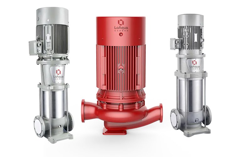
LeAqua’s LS/LC vertical multistage pump range is positioned for building water supply, industrial boosting, reverse osmosis, fire protection and liquid transfer. The published range covers approximately 0.4–240 m³/h, with heads up to 370 m depending on model and number of stages. Stainless steel, cast-iron and selected duplex configurations are listed.
This family is a candidate when the station needs higher pressure in a relatively compact footprint, such as a multi-level building or an industrial process. The vertical inline arrangement can simplify pipe routing, but the engineer still needs to check suction conditions, motor access, vibration, controls and the actual duty point.
2. Horizontal multistage pumps for compact water supply systems
HL/HF/HC/HE horizontal multistage pumps provide another option where a horizontal layout is more convenient. LeAqua lists flows up to 28 m³/h and heads up to 56 m for this family. These pumps can suit smaller building supply, industrial boosting, HVAC and reverse-osmosis duties when the required flow and head fall within the selected model.
The choice between vertical and horizontal multistage pumps should be based on duty point, available space, suction and discharge arrangement, maintenance access and control strategy. It should not be made from appearance or nominal tank size.
Plot the required duty on the chosen model’s curve and check the expected operating range. For a tank-fed pump, confirm the manufacturer’s suction requirements at the lowest permitted water level. A correctly sized motor cannot compensate for an unsuitable suction arrangement. See how engineers determine pump head for a water tank system for the distinction between elevation, friction losses and required pressure.
3. Double-suction pumps for high-flow stations
For municipal transfer, irrigation, industrial circulation, raw-water intake or other high-flow duties, a double-suction pump may be more appropriate. LeAqua’s SBS/SBSL series is described as a horizontal split-case design with a double-suction impeller. The published range extends to 10,000 m³/h and heads up to 200 m, depending on configuration.
The split casing is relevant to maintenance planning because inspection can be carried out with less disturbance to connected pipework than some other arrangements. A high-flow pump still needs a properly designed suction header, adequate approach conditions, lifting and access provisions, and an operating sequence that matches the storage tank and demand pattern.
4. Inline circulation pumps for closed or recirculating systems
EC vertical inline circulation pumps are aimed at HVAC, cooling towers, district heating, boiler feed and industrial circulation. The listed range reaches up to 750 m³/h and 55 m head, subject to model selection.
A circulation station is different from a tank-to-building booster. The engineer needs to calculate total circuit resistance, operating temperature, flow variation, bypass requirements and the control method. The tank may be part of the system, but the pump duty is governed by the complete circuit rather than storage volume.
5. Submersible sewage pumps for drainage and wastewater
Clean-water pump selection cannot be transferred to wastewater. LeAqua’s WQW/WQ/WQF submersible sewage pump range is described for sewage, industrial drainage and stormwater. Depending on the model, the published range reaches up to 2,000 m³/h flow and 90 m head, with solids passage up to 100 mm.
For this type of station, solids, access for cleaning, automatic coupling or mobile installation, motor protection and the properties of the pumped medium must be considered. A drainage sump or wastewater tank also needs level control, ventilation, overflow protection and safe maintenance procedures.
6. Pneumatic diaphragm pumps for special fluids
When the station handles chemicals, viscous liquids, coatings, adhesives or difficult wastewater, an air-operated double diaphragm pump may be considered. LeAqua’s pneumatic diaphragm pump range lists plastic, aluminum-alloy and stainless-steel configurations, with a published maximum flow of 41.7 m³/h and discharge pressure up to 8.6 bar depending on model.
These pumps use compressed air rather than a conventional electric motor. Selection must include the available air supply, wetted-material compatibility, diaphragm choice and discharge conditions. Hazardous-area suitability requires confirmation for the exact equipment and installation. They are a special-fluid option, not a universal replacement for a clean-water booster pump.
What are the advantages of integrating a water tank?
A storage tank can buffer changes or interruptions in the incoming supply while the pumps deliver water to the system. The duration depends on usable volume, replenishment and demand. Stored water alone does not guarantee delivery during a power outage: the pumping and backup-power strategy must also be defined.
Integrating a water tank with the pump station can provide four practical engineering advantages:
- Better suction and pipework coordination. Tank outlet positions, suction pipe size, valves and pump location can be reviewed as one arrangement.
- Clearer control logic. Tank level, pressure, flow, pump status and alarms can be assigned to the control cabinet before installation.
- More realistic maintenance planning. Access for tank inspection, pump removal, valve operation and control-cabinet servicing can be reserved in the layout.
- Fewer supplier interfaces. A coordinated package gives the project team one engineering scope for the main storage and pumping interfaces, even though civil, electrical and external works remain separate.
There is also a design trade-off. A larger tank is not automatically better. Oversized storage may increase water age, footprint, cleaning demand and project cost. Storage capacity should be based on the actual demand, required reserve, replenishment conditions and applicable project requirements. For potable or building water, material selection, inspection and cleaning arrangements must be confirmed for the intended use. The US EPA’s distribution-system resources address water-age management and storage-facility inspection and cleaning; these are useful considerations when reviewing storage volume and turnover. Fire-water storage, process water and wastewater should be treated as different design duties.
Pump selection at a glance
| Pump family | Duty to evaluate | Selection question |
|---|---|---|
| Vertical multistage | Pressure boosting in a compact layout | Does the model meet the required pressure and operating range? |
| Horizontal multistage | Smaller supply or process duties with a horizontal layout | Do the duty point, pipe connections and service access fit? |
| Double-suction split-case | High-flow transfer or circulation | Are suction conditions and lifting/maintenance clearances adequate? |
| Inline circulation | Recirculating HVAC or industrial circuits | What are the circuit resistance and fluid temperature? |
| Submersible sewage | Wastewater, drainage or stormwater | Are solids passage, sump control and cleaning access suitable? |
| Pneumatic diaphragm | Chemical, viscous or other special-fluid transfer | Are material compatibility and compressed-air supply confirmed? |
A six-step selection process
- Define the service: building supply, fire water, irrigation, circulation, drainage, sewage or special fluid.
- Calculate the duty point: establish design flow, total dynamic head, pressure zones and operating range.
- Check the fluid: confirm temperature, solids, corrosion exposure, viscosity and required materials.
- Coordinate the tank: review capacity, operating levels, outlets, suction conditions, overflow, drain and access.
- Design the controls: define duty/standby sequencing, level and pressure sensors, alarms and remote monitoring if required. Evaluate variable-speed operation where appropriate to the duty rather than assuming it is needed in every package.
- Verify delivery scope: separate factory-supplied equipment from foundations, power, external pipework, installation, commissioning and local approvals.
For fire-water projects, pump, driver, controller, reserve capacity and acceptance requirements must be checked against the applicable project standard and local approval process. A building-supply control sequence should not be copied into a fire-water system. Monitoring and cloud connectivity are project options; they do not establish fire approval or replace the specified local controls.
Questions to ask before requesting a quotation
- What is the required design flow and pressure at the outlet?
- What is the static elevation between the tank water level and the point of use?
- Is the medium clean water, fire water, wastewater, stormwater or a special fluid?
- What are the tank capacity, footprint, water levels and connection positions?
- Is duty-and-standby operation required, and what happens during power failure?
- Which local standards, inspection documents and acceptance tests apply?
- Who is responsible for foundation, external pipework, electrical work, installation and commissioning?
Practical questions about the station package
Does an integrated pump station mean the complete system arrives ready to operate?
Not necessarily. A coordinated package can reduce equipment-interface work, but foundations, incoming power, external pipework, drainage, site installation and commissioning may remain project responsibilities. The supply boundary should be written into the quotation.
Can integration reduce installation time or operating cost?
Coordinated connections and a defined supply scope can reduce avoidable interface work, but savings depend on the comparison scope, shipping arrangement, foundations, local labor and commissioning. Energy use depends on the actual duty profile and selected pump and control combination. A general time-saving or energy-saving percentage should not substitute for a project calculation.
Discuss your integrated pump station requirements
Selecting a pump for an integrated pump station is a system-design decision. The pump type must follow the duty, while the water tank, suction arrangement, controls, maintenance access and project boundaries are coordinated around it. LeAqua’s published pump range covers pressure boosting, high-flow transfer, circulation, wastewater and special-fluid applications. The project configuration should use the pump family that fits the actual duty. To discuss a suitable tank-and-pump configuration, request a project proposal with the design information listed above.
Product ranges and performance figures in this article are based on LeAqua’s published product pages and are subject to model selection and project verification. Final hydraulic, structural, electrical and code compliance checks should be completed by the responsible project engineers.