When selecting a pump for a water tank system, flow rate is usually the first number people look at.
But flow alone does not tell an engineer whether the pump is suitable.
A pump may deliver the required amount of water and still fail to provide enough pressure at the point of use.
That is why engineers also need to determine the required pump head.
Pump head is related to the amount of pressure the pump must provide to move water through the system while overcoming elevation differences and hydraulic losses.
For a water tank system, the calculation may involve:
- Tank water level
- Elevation difference
- Pipe length
- Pipe diameter
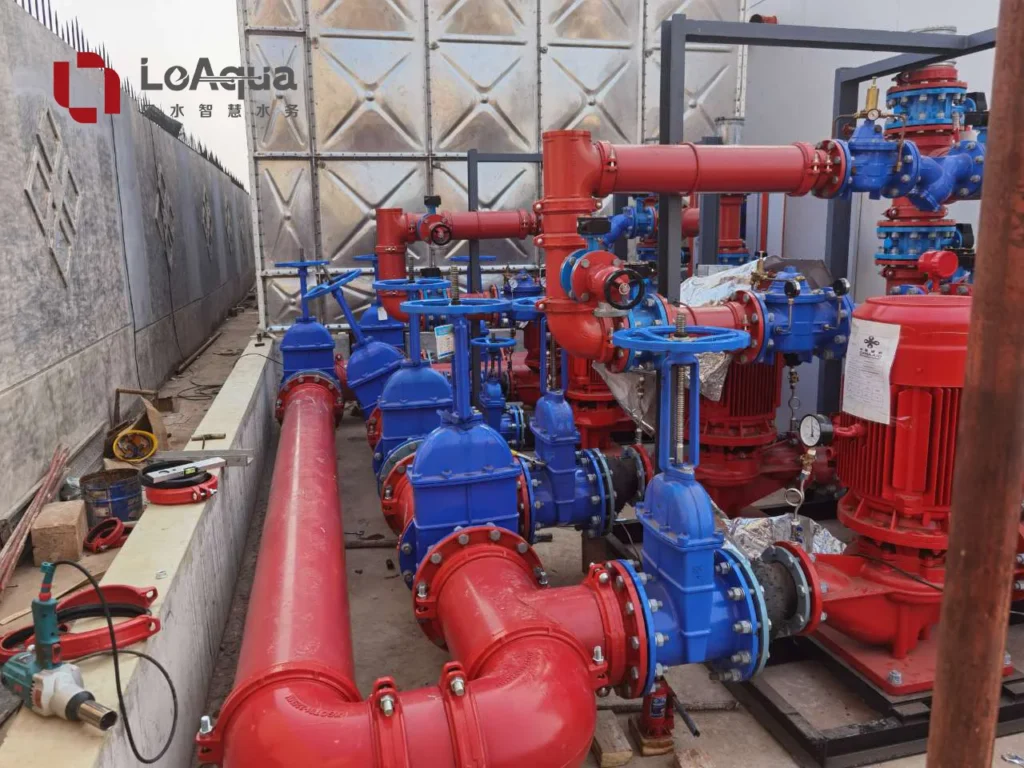
- Fittings and valves
- Required pressure at the outlet
- Operating flow rate
The exact calculation depends on the project.
The basic principle, however, is straightforward:
The pump must provide enough head to move the required flow through the complete system and still maintain the required pressure where the water is needed.

1. Start With the Required Water Flow
Before calculating pump head, engineers need to know the required flow.
Flow may be determined from:
- Building demand
- Fire protection requirements
- Industrial process requirements
- Peak water consumption
- Equipment requirements
For example, a domestic water system may have a different design flow from a fire protection system.
The flow rate is therefore established from the actual application.
A pump should then be evaluated at that required operating point rather than selected from the maximum flow shown in a catalogue.
This is important because pump performance changes with operating conditions.
2. Calculate the Elevation Difference
One of the first contributors to pump head is elevation.
Imagine a storage tank located on the ground and water being delivered to an upper floor.
The pump needs to overcome the vertical difference between the water level in the tank and the required outlet.
The greater the elevation difference, the greater the required head.
This is why high-rise buildings can require much higher pump head than low-rise buildings even when their water storage volume is similar.
For sites with significant changes in terrain, the same issue can occur horizontally distributed across the project.
A remote pumping system may have storage at a lower elevation and water demand at a higher point.
Engineers therefore need to establish the relevant elevation difference before selecting the pump.
3. Account for Pipe Friction Losses
Water loses pressure as it flows through a pipe.
The amount of loss depends on factors such as:
- Pipe length
- Pipe diameter
- Flow rate
- Pipe roughness
- Water properties
Longer pipe networks generally create greater friction losses.
Smaller pipes can also produce higher losses when carrying the same flow.
This becomes particularly important for large sites.
A water tank located close to a pump room may require a relatively simple distribution arrangement.
A remote wind farm, solar plant or industrial facility may have a much longer fire water network.
In such cases, pipe friction can become an important part of the pump head calculation.
This is also why engineers should not choose pumps based only on the distance between the tank and the building.
The complete pipe network needs to be considered.
4. Include Losses From Fittings and Valves
Pipes are not the only source of hydraulic loss.
The system may contain:
- Elbows
- Tees
- Reducers
- Valves
- Strainers
- Check valves
- Other fittings
Each component can contribute additional pressure loss.
A system with many fittings may therefore require more pump head than a simple straight pipe run of the same length.
For a detailed design, engineers calculate or estimate these losses as part of the total system head.
This is one reason the pump should be selected after the pipe arrangement has been established.
5. Consider the Required Pressure at the Point of Use
The pump also needs to provide enough pressure at the point where the water is actually required.
For example, a building may need a specified pressure at a fixture or distribution point.
A fire protection system may require the appropriate pressure at the most demanding hydrant or other outlet.
So the calculation is not simply:
Tank → Pipe → Outlet
It is:
Tank → Elevation → Pipe Losses → Fittings → Required Outlet Pressure
The pump must provide enough total head to satisfy all of these requirements at the design flow.
This is one of the most important differences between a catalogue-based pump selection and a system-based engineering selection.
6. Understand Static Head and Dynamic Head
Engineers often distinguish between the static and dynamic components of the system.
Static Head
Static head is associated with the elevation difference between the relevant water levels or pressure points.
It is present because of the physical position of the system.
Dynamic Losses
Dynamic losses occur while water is flowing through:
- Pipes
- Fittings
- Valves
- Other components
The actual pump requirement therefore depends on both the physical layout and the operating flow.
A system with a large elevation difference may have significant static head.
A long distribution network may have relatively modest elevation but significant friction losses.
Both conditions can lead to a substantial pump head requirement.
7. Tank Water Level Can Affect Pump Conditions
The tank itself also needs to be considered.
Water level is not always constant.
For example:
- The tank may be nearly full at one time.
- The water level may fall during extended demand.
- The pump suction conditions can change as the level changes.
Engineers therefore need to understand the operating range of the tank.
This is particularly important for systems where the pump is directly connected to the storage tank.
The design should consider the lowest relevant water level and the required suction conditions rather than using only the maximum water level.
Tank configuration, suction pipe arrangement and connection details can all affect pump operation.
8. Why Pump Flow and Pump Head Must Be Selected Together
Flow and head are not independent numbers.
A pump operates according to a performance curve, and its actual operating point depends on the system.
For example, a pump may be capable of producing a high flow under low-head conditions but deliver a smaller flow as required head increases.
This means that selecting a pump by saying:
“We need 60 L/s.”
is not enough.
The engineer also needs to know:
“At what head must the pump provide those 60 L/s?”
The intersection between the pump performance and the system requirement determines the practical operating point.
This is why pump selection should be based on the design duty point.
9. Site Conditions Can Change the Required Pump Head
The same tank and pump flow can require different pump head in different projects.
Consider two systems with:
- The same tank capacity
- The same required flow
Project A has:
- Short pipework
- Small elevation difference
- Few fittings
Project B has:
- Long pipework
- Greater elevation
- More valves and fittings
The pump flow requirement may be identical.
The required head may not be.
This is particularly relevant to remote infrastructure projects.
A wind farm, solar plant or industrial site may have equipment distributed across a large area.
In these cases, the pumping system needs to be designed around the actual site geometry.
For remote renewable energy applications, see 【Why Water Storage Design Is Different for Remote Renewable Energy Projects 】.

10. What Engineers Should Check Before Selecting a Pump
Before approving a pump for a water tank system, the project team should normally have:
- Required flow
- Required pressure
- Elevation difference
- Pipe route
- Pipe diameter
- Pipe length
- Major fittings
- Tank water level range
- Required operating conditions
They should also know whether the system requires:
- Duty pump
- Standby pump
- Jockey pump
- Variable-speed control
- Automatic operation
- Remote monitoring
For fire protection systems, the final pump configuration must also follow the applicable project standards and authority requirements.
A Simple Pump Head Calculation Framework
For preliminary engineering discussions, the system can be understood as:
Required Pump Head ≈ Static Head + Pipe/Fitting Losses + Required Residual Pressure
This is a simplified framework rather than a substitute for detailed hydraulic calculations.
The actual design may require additional considerations depending on the project.
What matters is that pump head is derived from the complete hydraulic system, not chosen from the tank capacity alone.
Why This Matters for a Water Tank With Pump System
A water tank stores the required volume.
The pump moves that water.
The pipe network distributes it.
The control system manages operation.
These components are closely connected.
For this reason, projects that require a tank and pumping system to operate as one package can benefit from considering the equipment together from the beginning.
For larger projects that combine storage, pumps, control and monitoring, see 【Integrated Pump Station】
Final Thoughts
Pump head is not a number that can be selected independently from the water tank system.
Engineers determine it from the relationship between:
Flow + Elevation + Pipe Losses + Required Pressure
The same pump flow can require very different head depending on the project.
That is why a proper water supply design looks at the complete hydraulic path from the storage tank to the point of demand.
For projects where storage and pumping need to be coordinated, the tank and pump should be considered together rather than selected as two unrelated products.
The better question is not:
“Which pump has enough flow?”
It is:
“Which pump can provide the required flow and pressure under the actual system conditions?”