Water tank pump suction design should be completed before the tank nozzles, suction pipework and pump are finalized. The key checks are the lowest operating water level, the pump centerline, suction-side losses, air entrainment, inlet submergence and the pump’s required NPSH at the actual duty point.
This guide focuses on centrifugal or other rotodynamic pumps used with water storage tanks. Positive-displacement pumps require a different suction analysis. The final arrangement should be checked against the selected pump data, the project’s hydraulic design and the applicable local requirements.
What is the correct approach to water tank pump suction design?
Quick answer: Start with the lowest operating water level, not the tank overflow level. Confirm the elevation between the water surface and pump datum, calculate suction-side losses, compare NPSHA with the pump’s NPSHR at the required flow, and arrange the tank outlet and suction piping so that air pockets, vortices and avoidable turbulence are not introduced.
The pump suction is part of the hydraulic system. It is not simply a pipe connected to the lowest tank outlet. A tank may have adequate nominal capacity and still provide poor pump suction conditions if the outlet is too small, the suction pipe contains a high point, the water level falls below the assumed level or the inlet creates a vortex.
Hydraulic Institute guidance treats NPSH as a system-and-pump relationship. The system must provide enough absolute pressure at the pump suction, while the pump manufacturer provides the NPSH required for the selected pump, speed and operating point. The two values should be reviewed together rather than considered separately. The Hydraulic Institute explanation of NPSH margin also makes clear that margin should be selected for the application and operating conditions, rather than copied as one universal percentage.
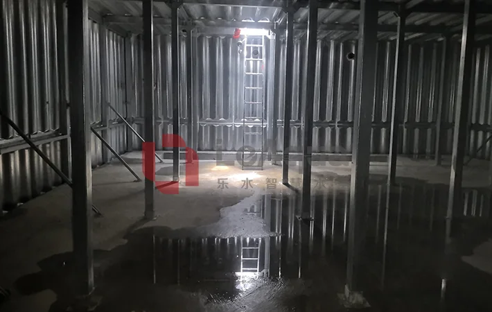
NPSHA and NPSHR: what is the difference?
NPSH is normally discussed using two values:
- NPSHA — Net Positive Suction Head Available: the absolute pressure head available at the pump suction under the actual system conditions.
- NPSHR — Net Positive Suction Head Required: the minimum suction head the selected pump requires at a specified flow, speed, fluid and performance condition.
For an open water tank, a simplified relationship is:
NPSHA ≈ atmospheric pressure head + static water-level head − vapor-pressure head − suction-side losses
For a closed or pressurized tank, the gas pressure above the water surface also affects the available head. The reference elevation must be clear: engineers normally compare the available head at the pump suction datum with the pump manufacturer’s NPSHR curve.
NPSHR is not a universal value for all pumps. It changes with pump model, impeller, speed, flow rate and test basis. The required value should therefore be taken from the selected pump’s performance documentation, not copied from another project. Hydraulic Institute’s pump definitions define NPSHR as a manufacturer- or supplier-provided value for a specified flow, speed and pumped liquid.
The available head should be calculated for the operating cases that can reduce suction conditions, including low tank level, maximum required flow, high water temperature, low atmospheric pressure, dirty strainers and unusual valve positions. Hydraulic Institute’s NPSH and pump operating-region guidance explains why operation away from the preferred operating region can require additional attention to NPSH margin.
How does cavitation occur in a tank and pump system?
Cavitation can occur when the local absolute pressure at the pump inlet or inside the impeller falls to or below the liquid’s vapor pressure. Vapor bubbles form in the low-pressure region and then collapse as the liquid moves into a higher-pressure region.
Typical warning signs include unusual noise, vibration, unstable flow, a drop in pump performance and progressive damage to hydraulic components. These symptoms do not prove that cavitation is the only problem. Air entering through a loose connection, a vortex at the tank outlet, a blocked strainer, pump recirculation or mechanical damage can create similar symptoms.
The practical objective is not to solve cavitation after commissioning. It is to prevent the suction system from reaching an operating condition in which the pressure at the pump inlet becomes too low.
What should be checked in the water tank inlet arrangement?
1. Use the minimum operating water level
The overflow level or geometric top of the tank is not normally the correct level for a conservative suction calculation. Use the lowest water level at which the pump is expected to operate. This level should be coordinated with:
- the effective tank capacity;
- the pump start and stop levels;
- the low-level alarm or trip;
- the position of the suction outlet;
- any reserved fire-water or process-water volume; and
- the operating sequence for duty and standby pumps.
The distinction between nominal and effective water tank capacity is important because water that exists geometrically in the tank may not be available to the pump throughout the approved operating range. The nominal versus effective water tank capacity guide explains why the two values should not be treated as interchangeable.
2. Check the pump centerline and static head
If the pump is below the tank water level, the system may have a flooded suction condition. If the pump is above the water level, the system operates with suction lift and has less available head. The calculation should use the actual pump datum and the lowest relevant water surface, not a convenient elevation taken from a preliminary layout.
Pump room arrangement, tank support height, maintenance access and structural levels can all change the available static head. This is why pump selection and tank layout should be coordinated before the final foundation and pipework drawings are released.
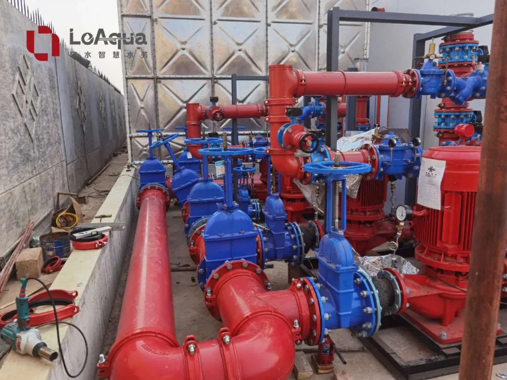
3. Keep the suction path simple and free from trapped air
Suction pipework should be arranged to avoid unnecessary fittings, abrupt changes in direction and high points where air can collect. The required pipe slope depends on whether the pump has flooded suction or suction lift, the pump manufacturer’s instructions and the project arrangement. For suction-lift lines, the KSB guidance on air pockets and the relevant pump installation manual should be checked together.
Do not assume that a short pipe is automatically a good suction pipe. A short pipe with an unsuitable reducer, poorly located elbow, undersized strainer or trapped air pocket can still produce unstable inlet conditions.
Where a reducer, elbow or flexible connector is required near the pump, use the selected pump manufacturer’s recommended arrangement and provide adequate straight approach where specified. Fixed rules such as one universal straight-length ratio should not replace the pump supplier’s data or the project hydraulic review.
4. Review the tank outlet, inlet submergence and vortex risk
The tank suction outlet needs enough submergence at the minimum operating level to limit surface vortices and air entrainment. The required submergence depends on outlet geometry, flow rate, tank shape, nearby walls, screens, internal baffles and the water level above the outlet. The Hydraulic Institute submergence reference can be used as a starting point, but the final value should be checked against the actual tank geometry, flow and pump intake arrangement.
If the tank inlet and pump suction are arranged too close together, incoming water may travel directly to the outlet without providing the intended storage or may disturb the suction flow. The water tank connection schedule should therefore coordinate inlet direction, outlet position, internal separation, overflow and drain arrangement.
The water tank connections guide can be used together with the pump layout to review these interfaces before fabrication.
5. Account for strainers, valves and filters
Every component on the suction side contributes to pressure loss. The calculation should include the actual internal diameter, pipe length, fittings, isolation valves, check or foot valves where used, strainers, filters and any temporary commissioning arrangement.
Strainers and filters should be selected for the required flow and maintained in a condition consistent with the design calculation. A clean strainer may be acceptable during factory testing but create excessive loss after debris accumulates on site.
External suction pipework and valves should also have independent support where required. The tank nozzle should not be treated as a structural support for heavy pipework or equipment unless the approved design specifically allows it.
A practical NPSH check for a water tank pump
The following sequence is suitable for a preliminary project review:
- Define the fluid. Confirm water temperature, density, dissolved conditions and any additives that affect vapor pressure or hydraulic losses.
- Define the operating range. Record minimum and normal tank levels, required flow, start-up conditions, duty and standby combinations, and any future operating case.
- Set the pump datum. Confirm the pump centerline or suction flange elevation used for the calculation.
- Calculate suction losses. Include pipe friction, fittings, valves, strainers, filters, reducers and the expected operating condition of those components.
- Obtain the pump NPSHR. Use the selected pump curve or technical data for the actual speed, flow and configuration.
- Review the margin. Compare NPSHA and NPSHR using the project’s application guidance. Do not apply a universal margin without checking the pump type, service and operating range.
- Check physical arrangement. Confirm submergence, air release, pipe slope, access for cleaning and the absence of unintended high points.
- Review abnormal conditions. Consider low water level, high temperature, reduced atmospheric pressure, blocked strainers, parallel pump operation and temporary commissioning connections.
The Hydraulic Institute’s pump and pump-system definitions and the selected pump manufacturer’s performance documentation provide useful reference points for this review. The project engineer should still use the actual tank, piping and site data.
What information should be sent to a water tank pump supplier?
| Information | Why the supplier needs it |
|---|---|
| Tank nominal and effective capacity | Defines the operating volume and available water levels |
| Minimum, normal and maximum water levels | Establishes the static head range |
| Pump duty flow and head | Allows the pump operating point to be checked |
| Pump centerline or suction flange elevation | Defines the elevation reference for NPSHA |
| Water temperature and fluid condition | Affects vapor pressure and hydraulic behaviour |
| Suction pipe diameter, length and fittings | Determines suction-side losses |
| Strainer, filter and valve arrangement | Adds actual component losses and maintenance considerations |
| Tank outlet size, elevation and internal arrangement | Helps review submergence and inlet flow conditions |
| Site elevation and atmospheric conditions | Affects available absolute pressure |
| Duty/standby and operating sequence | Identifies the worst-case pump combination |
For quotation work, this information should be sent with the rest of the water tank RFQ information. A supplier can coordinate tank and pump interface information, but the final hydraulic design should remain aligned with the project’s responsible engineer and the approved pump selection.
How can LeAqua support suction coordination?
For a tank-and-pump project, LeAqua can review the tank capacity, operating levels, suction connection, pump duty and site constraints as part of a technical proposal. This is more useful than selecting the tank first and asking the installer to solve the pump suction after delivery.
Project note: A supplier can provide tank connection data, pump performance information and interface drawings. The project team still needs to confirm the complete suction system, local design requirements, installation conditions and final acceptance criteria.
The pump head calculation should be reviewed together with suction conditions. The water tank pump head guide explains the discharge-side and system-head questions that should be coordinated with this suction review.
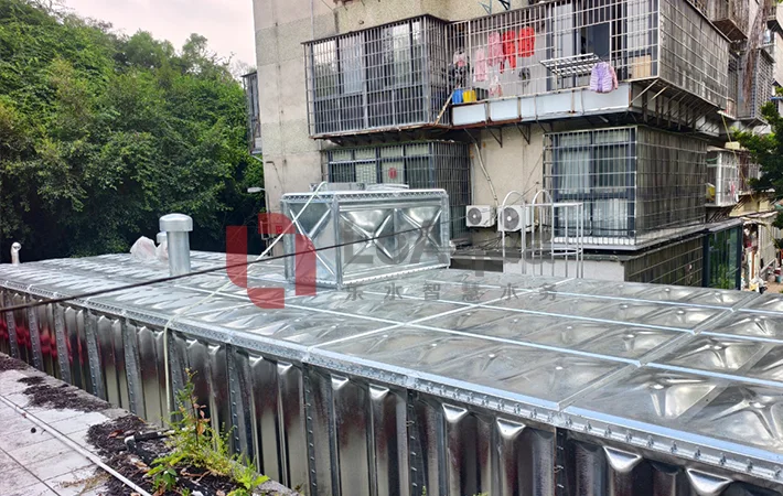
Common mistakes to avoid
Using the full tank level in every calculation
This can overstate the available suction head. The minimum operating level and the actual pump operating sequence are normally more important for a conservative review.
Treating NPSHR as a fixed pump property
NPSHR changes with flow, speed and pump configuration. Always use the curve or data for the selected pump and duty point.
Adding a strainer or valve after the calculation
Additional suction-side components increase losses. Any change to the arrangement should trigger a review of the NPSHA calculation.
Assuming a larger tank automatically prevents cavitation
A larger tank may provide more water volume, but it does not automatically correct a low pump position, an undersized suction pipe, excessive fittings, poor submergence or high water temperature. Hydraulic Institute pump-piping guidance also notes that air pockets, short-radius elbows and insufficient submergence can degrade inlet conditions even when the tank itself is large enough.
Calling every noisy pump a cavitating pump
Noise and vibration require diagnosis. Air leakage, vortexing, recirculation, bearing problems and mechanical damage can have similar symptoms. The operating data and physical inspection should be reviewed before selecting a remedy. Grundfos’ NPSH overview describes the link between low inlet pressure, vapor formation, noise and pump damage, but the actual fault still needs to be confirmed on site.
Conclusion
Reliable water tank pump suction design connects four items: the minimum operating water level, the physical inlet arrangement, the suction-side pressure losses and the selected pump’s NPSHR. The best time to complete these checks is before the tank nozzles, foundation elevations and pump room pipework are finalized.
For a project quotation or technical review, prepare the tank levels, pump duty, pump elevation, suction pipe arrangement, strainer and valve data, fluid temperature and site conditions. This gives the tank and pump supplier enough information to identify interface risks before manufacturing and installation.