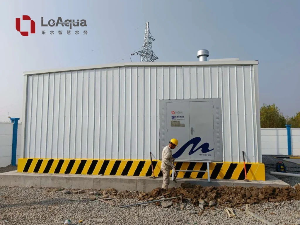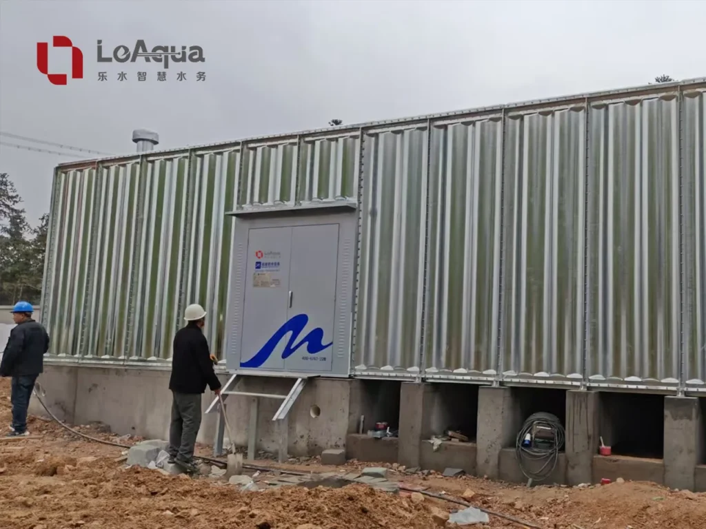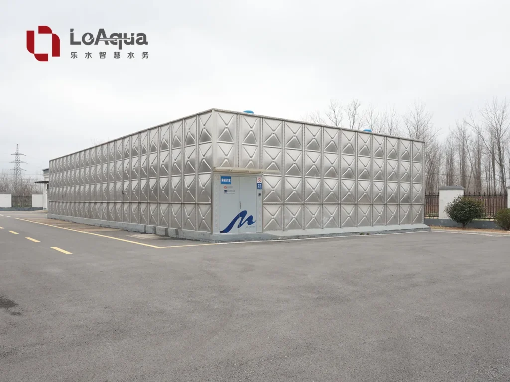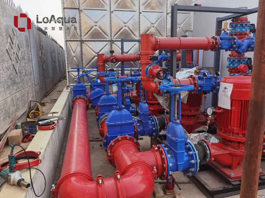
Water tank connections determine how water enters, leaves, overflows, drains and interacts with pumps and controls. A tank may have the correct material and nominal capacity but still create site problems when its nozzle sizes, elevations or directions do not match the hydraulic design and external pipework.
Engineers should therefore treat water tank connections as part of the system design, not as accessories to add after selecting the tank. The connection schedule should coordinate operating water levels, refill flow, pump suction, safe overflow discharge, cleaning, ventilation, instruments and maintenance access before manufacturing begins.
This guide explains what each connection does and what information a tank supplier needs. For the broader choice of application, material, structure and capacity, start with the LeAqua Water Tank Selection Guide.
Which Connections Does a Water Tank Need?
| Direct answer: Most project tanks need an inlet, service outlet or pump suction, overflow, drain or washout, and vent. They may also need level sensors, alarms, recirculation, test return, sampling or dedicated fire-water connections. The application and hydraulic design determine the final set, sizes and locations. |
The list changes with the service. A potable-water break tank, an industrial process tank and a fire-water tank can use similar physical fittings while assigning them different duties. The approved drawings should name every connection by function so the factory, installer and commissioning team use the same terminology.
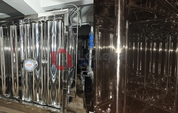
Water Tank Connection Schedule at a Glance
| Connection | Primary function | Key design inputs | Show on the drawing |
| Inlet / fill | Refills the tank | Available flow and pressure, control method, refill time, water source | Size, elevation, direction, flange or thread, valve and control interface |
| Outlet / pump suction | Supplies the downstream system or pump | Design flow, minimum water level, suction conditions, pump arrangement | Size, centerline, direction, internal fitting and isolation boundary |
| Overflow | Carries excess inflow to a safe discharge point | Credible incoming flow, control response, discharge route and local requirements | Size, invert level, route, termination and protection details |
| Drain / washout | Empties the tank and removes cleaning water | Tank geometry, cleaning plan, drainage capacity and disposal route | Low-point location, size, valve access and discharge point |
| Vent | Allows air to enter and leave as the water level changes | Maximum filling and drawdown rates, pressure limits and hygiene requirements | Size, location, termination, weather and insect protection |
| Level instruments | Controls filling and reports operating status | Start/stop levels, alarms, reserve levels, signal type and control philosophy | Sensor type, elevations, tags, cable route and panel interface |
| Optional services | Supports return flow, sampling, testing or compartment operation | Process, fire, commissioning and maintenance requirements | Function, size, elevation, direction and responsibility |
This schedule creates a common design language and gives every discipline a defined set of interfaces to review alongside the hydraulic calculations, pump data and local approval requirements.
Why Engineers Should Coordinate Connections Before Manufacturing
Connection changes can affect panel fabrication, internal supports, useful storage volume, external pipe routes and the foundation layout. On a sectional tank, the supplier also needs to place openings without weakening panel joints or conflicting with internal structural components. Early coordination reduces site cutting, adapter pieces and pipe offsets.
The design team should freeze the major nozzle schedule together with the tank dimensions and operating levels. A complete review normally involves the hydraulic or plumbing engineer, pump supplier, tank supplier, civil or structural engineer, controls contractor and site installer. The water tank supply scope guide helps procurement teams assign these interfaces in the quotation.
- Confirm the connection function and tag, not only the pipe diameter.
- Use one elevation datum across the tank, foundation and external pipe drawings.
- Coordinate flange standards, pressure classes, materials and gasket requirements.
- Reserve working space for valves, instruments, bolts and future maintenance.
- Record which party supplies internal fittings, external valves, flexible joints and pipe supports.
How Should Engineers Specify the Water Tank Inlet?
The inlet must refill the tank at the required rate without creating uncontrolled pressure, excessive turbulence or an unreliable level-control sequence. Start with the available source flow and pressure, required recovery time and normal operating range. Then select the valve and control method that fit the water supply system.
Coordinate the inlet with level control
A mechanical float valve, actuated valve, pump or other filling device needs clear start and stop levels. The controls designer should also define high-level action and the response to a failed valve or sensor. Where the project uses two compartments, the design should explain whether each compartment fills independently or through a common arrangement.
Consider water movement and hygiene
Inlet location influences circulation inside the tank. The designer can use the inlet and outlet arrangement to reduce direct short-circuiting and support regular turnover, while the operating plan controls retention time and cleaning. For potable-water projects, use the World Health Organization Guidelines for Drinking-water Quality and the applicable local water regulations as part of the water-safety review. European projects should also identify the national requirements that implement the EU drinking-water framework.
How Should Engineers Design the Outlet or Pump Suction Connection?
| Direct answer: Design the tank outlet around the required flow, minimum operating water level and pump suction conditions. The engineer and pump supplier should coordinate connection size, elevation, internal geometry, suction piping and available head so the pump receives stable flow throughout its approved operating range. |
A pump does not respond to nominal tank capacity; it responds to the hydraulic conditions at its suction connection. The review should include static head at the lowest operating level, pipe losses, fittings, isolation valves, strainers where applicable, fluid temperature, pump elevation and the manufacturer’s net positive suction head requirements.
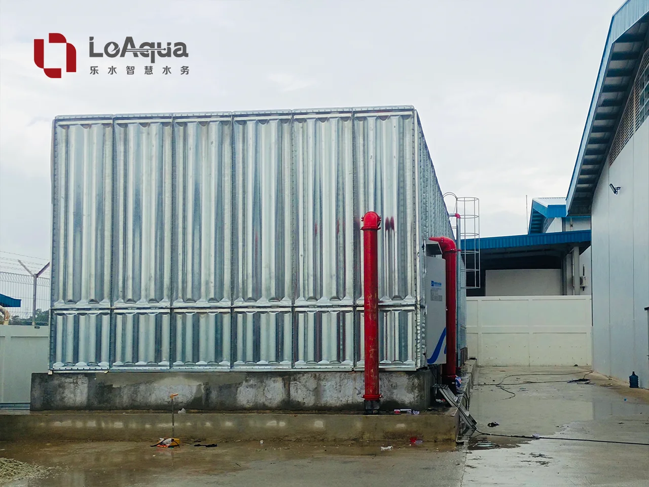
The project team should also review flow distribution near the outlet. Depending on the application, the design may use an internal bellmouth, anti-vortex arrangement, separate suction connections or a common header. The selected pump and governing standard determine the final geometry. For fire-pump installations, coordinate the tank interface with the applicable edition of NFPA 20 or the locally adopted fire-pump standard.
- Keep the suction route as direct as the approved layout allows.
- Place valves and removable fittings where technicians can operate and service them.
- Support external pipework independently so it does not impose uncontrolled loads on the tank panel.
- Coordinate flexible connections, anchors and movement allowances with the structural and piping design.
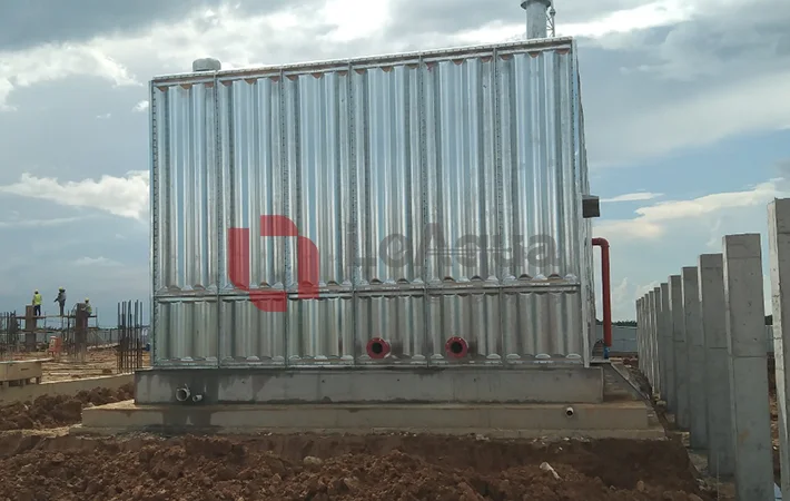
What Does the Water Tank Overflow Need to Do?
The overflow provides a safe path when inflow raises the water above the maximum operating level. Its design starts with the credible incoming flow and the filling-control response. The project engineer should size the complete path, including fittings and discharge piping, rather than selecting a tank opening in isolation.
Route overflow water to a visible and safe location with enough drainage capacity. The discharge should not damage the foundation, flood equipment, create a slip hazard or allow contaminated water to return to the tank. Potable-water projects may require screened or otherwise protected terminations and separation from drainage systems. Apply the relevant local plumbing and water-quality rules to those details.
A continuously available overflow path also supports fault detection. A visible discharge can alert the operator to a failed inlet valve, incorrect level signal or control problem. Connect that physical indication with a high-level alarm where the operating strategy requires remote response.
How Should the Drain or Washout Connection Work?
The drain allows the maintenance team to empty the tank and remove water generated during cleaning. Place it at a practical low point and coordinate the floor or panel geometry so the team can remove as much residual water and sediment as the design requires. A drain that sits above the lowest area can leave avoidable manual pumping or wet-vacuum work.
The site drainage system must accept the planned discharge rate and water quality. The connection schedule should identify the drain valve, access space, discharge route and any treatment or controlled-disposal requirement. Maintenance planning should also cover safe isolation, lighting, ventilation and entry procedures. In the United States, OSHA’s permit-required confined-spaces standard provides an important regulatory reference for qualifying spaces and entry controls; each project must use the rules that apply at its location.
Why Does a Water Tank Need a Vent?
| Direct answer: A tank vent lets air leave during filling and enter during drawdown. Engineers size and protect the vent for the maximum expected air movement so pressure or vacuum does not build up inside the tank. The termination also needs weather, insect and contamination protection appropriate to the stored water. |
The vent design should reflect both normal and abnormal operating cases. Fast pump drawdown, rapid filling, simultaneous pump operation or a restricted overflow can change the required air path. The designer should also confirm whether the overflow contributes to venting under the governing specification or whether the tank needs a separate vent sized for the full duty.
Place the vent where technicians can inspect and clean its protective components. Outdoor tanks may need a termination that sheds rain, while potable-water systems may require screens and hygienic detailing. Avoid routing the vent into a space that exposes the stored water to dust, fumes or process contaminants.
How Do Level Sensors and Alarms Fit the Connection Plan?
Level instruments turn a storage tank into an operating system. They can start and stop refill equipment, protect pumps, preserve a dedicated reserve and alert operators before an overflow or low-water condition affects service. The controls team should define every setpoint by elevation and function, then use the same values in the tank drawing, control narrative and commissioning sheet.
| Typical level | Possible function | Coordination question |
| High-high level | Alarm or protective action | Who receives the alarm and what action follows? |
| High / fill-stop level | Stops incoming flow or refill pump | What happens if the primary device fails? |
| Normal operating band | Controls refill cycling | Does the band provide the required turnover and reserve? |
| Low / fill-start level | Starts refill or signals low storage | Will the supply recover before demand reaches the minimum level? |
| Low-low level | Protects pumps or triggers emergency action | Which services stop, continue or transfer to another source? |
| Minimum usable level | Defines the bottom of effective storage | Do pump suction and reserve requirements support this elevation? |
Choose instrument technology according to the water, tank geometry, environment and maintenance capability. The project may use float switches, pressure-based transmitters, ultrasonic or radar devices, or another approved method. The specification should focus on measurable duties, signal interfaces, alarm behavior and access for calibration rather than naming a technology without an operating basis.
How Connections Affect Effective Water Tank Capacity
Water tank connections establish several elevations that influence usable storage. The overflow or maximum operating level defines the upper boundary, while the minimum usable suction level defines the lower boundary. Freeboard, reserve allocation, compartment walls and internal displacement can create additional differences between geometric volume and effective capacity.
For a simple rectangular tank, the vertical distance between the approved upper and lower operating levels helps define the usable volume across the plan area. Actual calculations should also account for the tank geometry and any volume that the design excludes. Label these levels and the resulting effective capacity on the approved drawing so procurement and engineering compare the same quantity.
- Nominal capacity describes the tank’s stated geometric or catalogue volume.
- Operating volume covers the water used during normal level cycling.
- Effective or usable capacity covers the volume available for the defined service between approved limits.
- Dedicated reserve remains protected for a stated emergency or service condition.
What Changes for a Fire-Water Tank?
A fire-water tank connects to a life-safety system, so the fire strategy and hydraulic design govern its effective capacity, suction arrangement, refill assumptions, alarms and test provisions. The connection schedule may include separate pump suctions, test return, fire-service fill, level alarms and compartment isolation, depending on the approved design.
NFPA 22 is one reference for water tanks used in private fire protection, while other jurisdictions use different standards and approval processes. Identify the governing standard, edition and authority at the start of the project, then coordinate the tank with the fire-pump requirements. LeAqua’s technical references page explains the company’s relevant engineering background without treating one standard as automatic approval in another market.
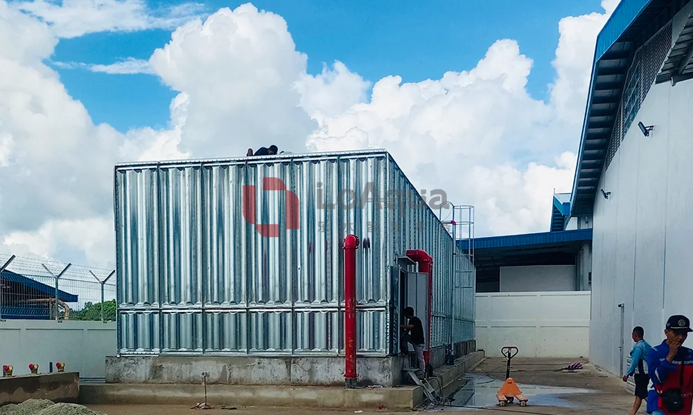
What Should the Approved Connection Drawing Show?
A useful general arrangement drawing allows the site team to position pipework before the tank arrives. It should show more than circles on a tank elevation. Each opening needs a unique tag and enough information for fabrication, installation and controls coordination.
- Tank external dimensions, panel arrangement, compartments and orientation
- Foundation or support datum and the elevation reference used for every connection
- Connection tag, service, nominal size, material and flange or thread standard
- Connection centerline or invert elevation, direction and projection
- Normal, minimum and maximum water levels, overflow level and effective capacity
- Internal fittings such as suction devices, diffusers or supports where applicable
- External valve, flexible-joint and pipe-support interfaces included in the supply
- Level instruments, alarm points, cable entries and control-panel references
- Access openings, ladders and maintenance clearances around valves and instruments
- Revision status and written approval before the supplier releases fabrication
For stainless steel sectional configurations, the LeAqua stainless steel water tank page provides an overview of available structures. The final connection arrangement still follows the approved project drawing because panel layout, supports and site pipework differ by order.
Coordinate the Tank and Pump System as One Hydraulic Interface
The outlet, minimum water level and pump suction line form one hydraulic path. Coordinating them together gives the pump supplier accurate inlet conditions and gives the tank supplier a confirmed nozzle elevation and loading interface. It also helps the controls designer align low-level protection with actual pump operation.
LeAqua can review a standalone tank or a coordinated tank-and-pump package when the project brief includes the effective capacity, design flow, head, operating levels, site layout and applicable standards. The integrated pump systems page shows how storage, pumping and controls can form one project-specific system rather than separate equipment selections.
Common Water Tank Connection Mistakes
- Sending only a tank capacity and asking the supplier to choose every connection
- Changing nozzle positions after panel fabrication or foundation construction begins
- Sizing an overflow opening without checking the complete discharge route
- Placing a suction connection without confirming the minimum operating level and pump data
- Using different elevation datums on tank, civil and pipework drawings
- Leaving no access to operate a valve, remove a sensor or replace a flange gasket
- Allowing external pipe weight or movement to act directly on a tank panel
- Showing instrument tags on the tank drawing but omitting their setpoints from the control narrative
- Combining fire, domestic or process services without defining how each reserve remains available
Frequently Asked Questions
Can the tank supplier select all connection sizes?
The supplier can propose practical openings and fabrication details, but the project engineer must provide the hydraulic duties and applicable requirements. Inlet flow, overflow duty, pump suction, drainage and control philosophy come from the complete system, not from tank capacity alone.
Should the overflow be larger than the inlet?
A simple diameter comparison does not confirm overflow capacity. The engineer should calculate the credible incoming flow and evaluate the full overflow path, including head, fittings, pipe length and discharge conditions. Local regulations may also set specific requirements for the connection and termination.
Can the drain and outlet use the same connection?
Some layouts may combine functions through an approved valve arrangement, while others need a dedicated low-point washout and a separate service outlet. The decision depends on hygiene, pump protection, maintenance, isolation and the required residual volume. Show the intended operating sequence on the piping diagram.
Where should the water tank vent terminate?
Terminate the vent in a clean, inspectable location where it can exchange air without admitting rain, insects, dust, fumes or other contaminants. The exact detail depends on the stored water, tank location and local requirements.
What information should a buyer send with an RFQ?
Send the tank service, effective capacity, dimensions or site limits, operating levels, connection schedule, design flow, pump duty, water quality, project location, applicable standards and supply boundary. The LeAqua water tank RFQ checklist provides a broader list for technical and commercial quotation preparation.
Final Connection Checklist Before Manufacturing
- Every connection has a unique tag, function, size, material and end standard.
- The drawing uses one confirmed elevation datum.
- Minimum, normal, maximum and overflow levels match the control narrative.
- The effective capacity matches the approved operating levels.
- The inlet and overflow duties reflect the credible filling condition.
- The outlet and pump suction arrangement match the pump data and minimum level.
- The drain route supports cleaning and safe disposal.
- The vent supports filling and drawdown and protects the stored water.
- The project team has coordinated external pipe loads, supports, movement and maintenance access.
- The buyer, engineer, supplier and installer have approved the same drawing revision.
Conclusion
Water tank connections link storage to the rest of the water system. When the project team coordinates the inlet, outlet, overflow, drain, vent, operating levels and controls before manufacturing, the approved tank drawing becomes a reliable installation document rather than a catalogue sketch.
For a project-specific review, send LeAqua the required effective capacity, tank application, site layout, connection schedule, pump duty, operating levels and applicable standards through the LeAqua contact page. The engineering discussion can then coordinate tank fabrication, external pipework and pump interfaces around the actual project.