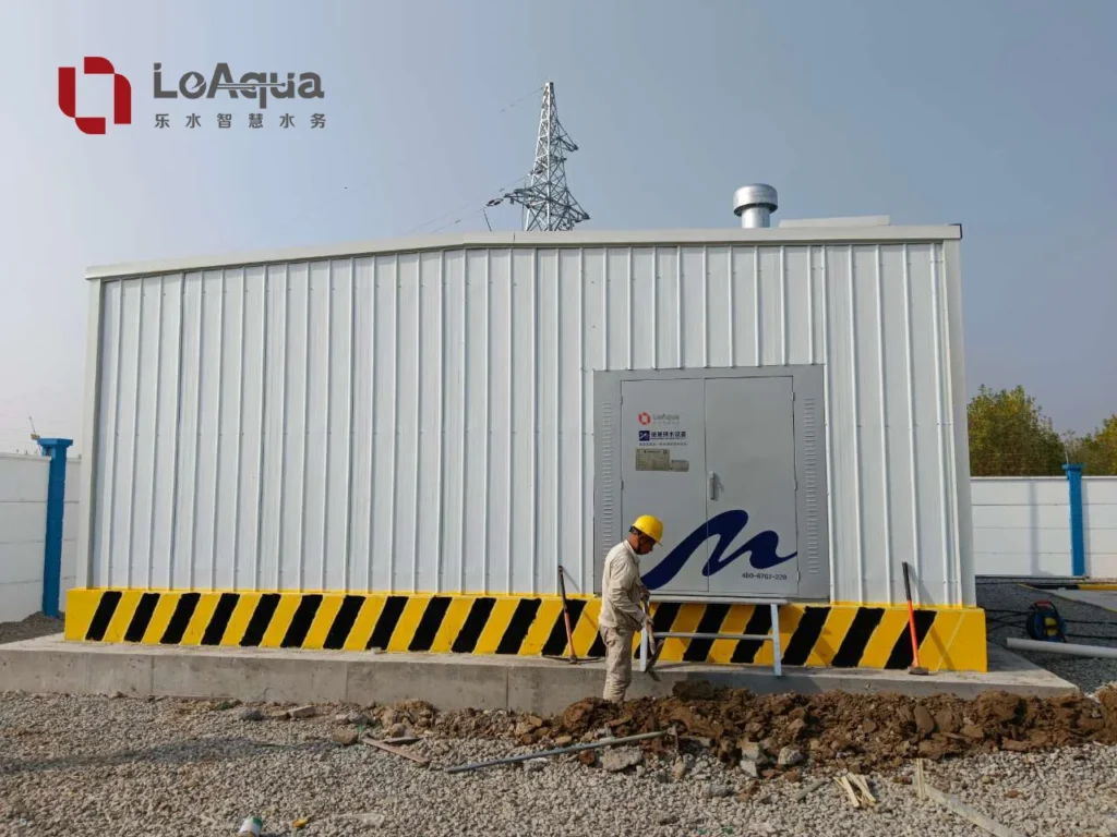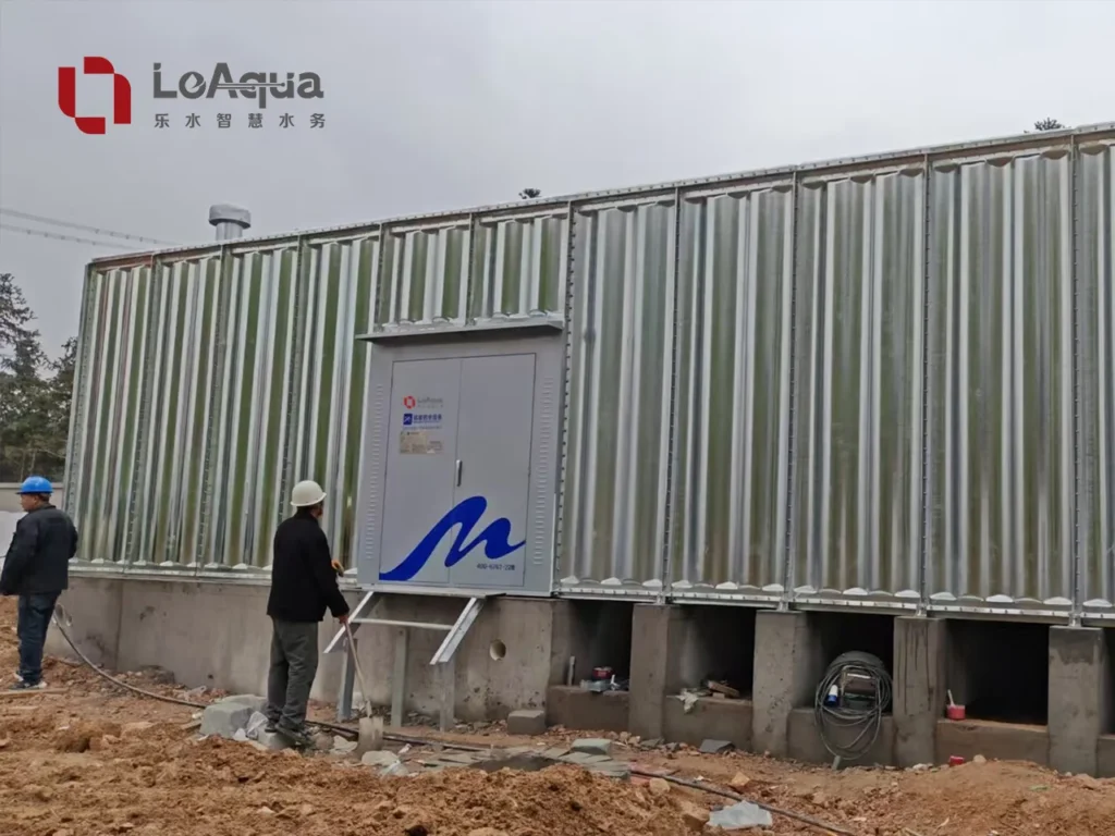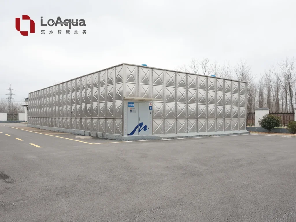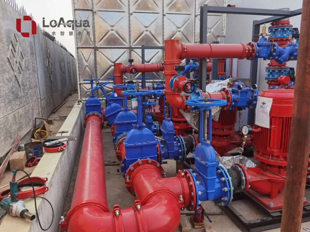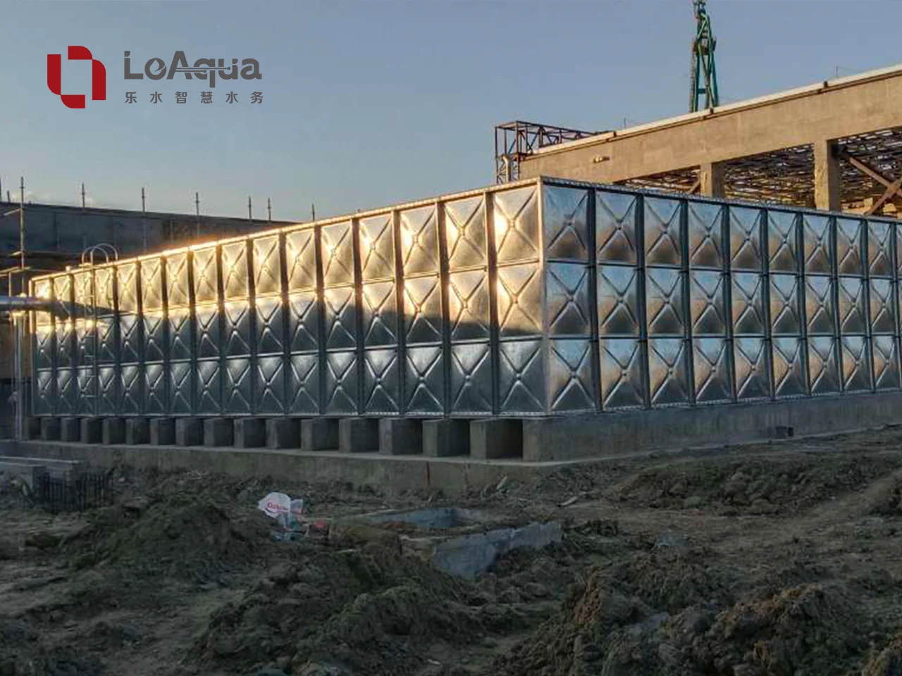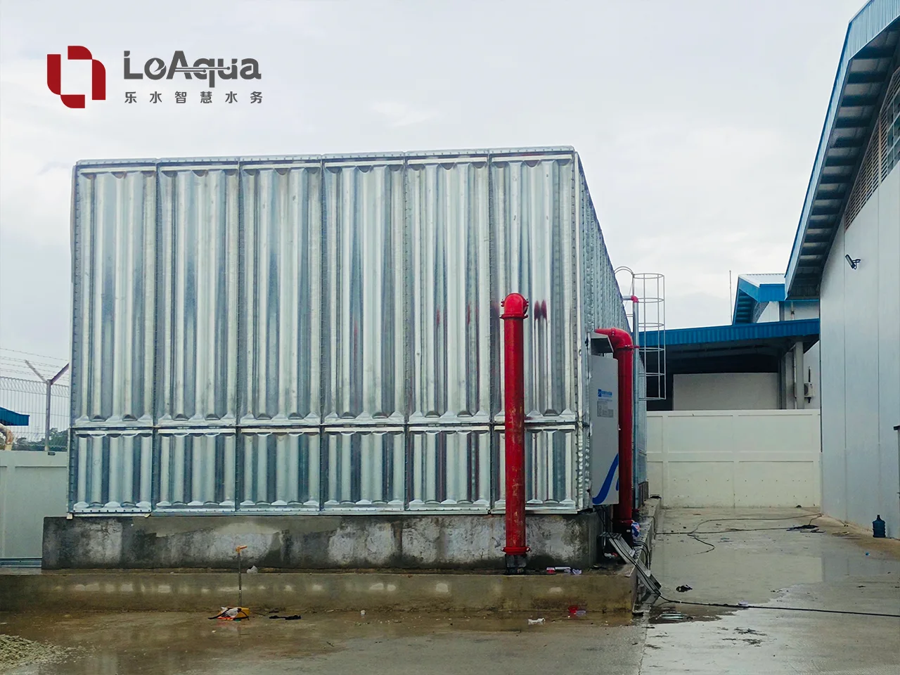
A sectional water tank foundation has to do more than provide a flat place for the tank. It must support the filled tank, match the tank footprint and support arrangement, allow the required connections and drainage, and leave enough space for assembly and maintenance.
The exact foundation requirements depend on the tank dimensions, operating levels, construction, site conditions and local structural design. A supplier can provide the tank loads and interface drawings, but the final foundation design should be coordinated with the project’s responsible structural engineer.
This guide explains what buyers, EPC contractors and MEP engineers should confirm before a sectional water tank is ordered or installed.
What foundation does a sectional water tank need?
A sectional water tank normally needs a level, adequately supported base designed for the tank in its operating condition. Depending on the site, this may be a reinforced concrete slab, a raised plinth, a steel support frame or another engineered support arrangement.
Quick answer: A sectional water tank foundation must support the filled tank, match the approved support layout, meet the required level and tolerance, and coordinate drainage, connections, access and local structural requirements. The final base design depends on the tank drawings and site conditions.
The correct choice is determined by the tank support layout and the building structure. The base must transfer the filled-tank reactions safely to the ground or supporting structure while maintaining the required elevation, levelness, drainage and access.
The foundation should be designed from the approved tank drawings and project data. A generic concrete pad sized only from the nominal tank dimensions can leave out wall projections, support points, access zones, pipework and maintenance clearance.
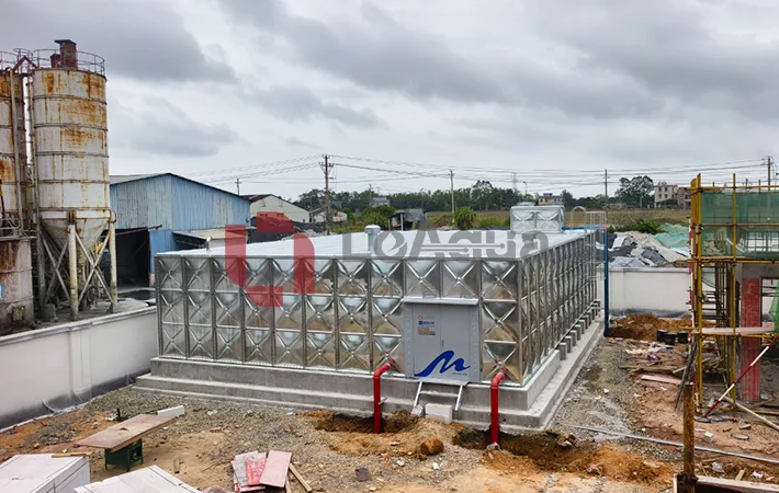
Why filled-tank load matters
Water storage creates a load that changes with the operating level. The structural review should therefore consider the tank when full, at its normal operating level and in any other condition required by the project design.
The load review may need to include:
- Stored water and the effective operating volume
- Tank panels, internal stays, roof, ladders and accessories
- Pipework, valves, level instruments and connected equipment
- Concentrated reactions at supports, rails or bearing points
- Wind, seismic, snow or other site-specific actions where applicable
- Empty-tank, maintenance and temporary construction conditions
The tank supplier should state the design basis and the reactions or distributed loads that the structural engineer needs. The structural engineer then checks the supporting slab, plinth, steelwork, soil bearing and restraints for the project location.
For this reason, “the tank weighs X” is not enough for foundation design. The project team needs to know how the load reaches the base and which load cases apply to the installation.
The main sectional water tank foundation requirements
| Requirement | Why it matters | What to confirm |
|---|---|---|
| Support arrangement | The tank may transfer load through a continuous base, rails or defined support points | Supplier drawing, support spacing and reaction data |
| Base level and flatness | Uneven support can affect panel alignment, seals and structural behaviour | Finished elevation, tolerances and survey method |
| Foundation footprint | The base must support the tank and allow the required edge, access and drainage zones | Internal tank dimensions, external dimensions and clearance plan |
| Bearing capacity | The ground or structure must carry the design reactions without unacceptable movement | Geotechnical or structural design information |
| Restraint and anchoring | Some installations require resistance to sliding, overturning or seismic actions | Anchor details and local design requirements |
| Drainage | Overflow, drain-down and cleaning water need a controlled route away from the base | Drain location, slope, channel and discharge point |
| Connection access | Inlet, outlet, overflow, drain and vent connections need working space | Connection elevations and maintenance access |
| Construction sequence | A sectional tank may be assembled after the base is complete | Delivery route, lifting plan and installation sequence |
Step 1: Freeze the tank capacity and dimensions
Foundation coordination should begin after the project has defined the required storage function. Confirm the nominal capacity, effective capacity, operating levels and any dedicated reserve before fixing the tank footprint.
The water tank selection guide can help organize the earlier decisions about application, material, structure and capacity. Once the tank type is selected, the foundation team needs the actual internal and external dimensions rather than a rounded capacity label alone.
A change from a low, wide tank to a taller tank can affect access, wind exposure, platform requirements and structural reactions even when the nominal capacity is similar.
Step 2: Match the base to the support layout
Sectional tanks are assembled from panels and connected into a designed structure. The base must match the support arrangement shown on the approved general arrangement or foundation interface drawing.
The review should check whether the tank bears continuously on a prepared surface or transfers load through defined rails, beams or supports. It should also confirm whether a raised base, curb, anti-vibration detail or separation layer is required by the project specification.
Do not infer the support arrangement from a photograph of another tank. Panel dimensions, tank height, internal reinforcement and connection details can change the reaction pattern.
Step 3: Check level, elevation and tolerances
Levelness is a practical installation requirement as well as a structural concern. A base that is out of tolerance can make panel assembly difficult, affect sealing and shift the final connection elevations.
Before delivery, the project team should agree:
- Finished foundation elevation
- Permitted level and flatness tolerances
- Survey reference points
- Repair procedure if the base is outside tolerance
- Protection of the finished surface before tank assembly
The approved drawing should also show the relationship between the foundation, access platform, surrounding floor and pipework. This avoids trying to correct elevation problems with improvised packing or unsupported pipe sections during installation.
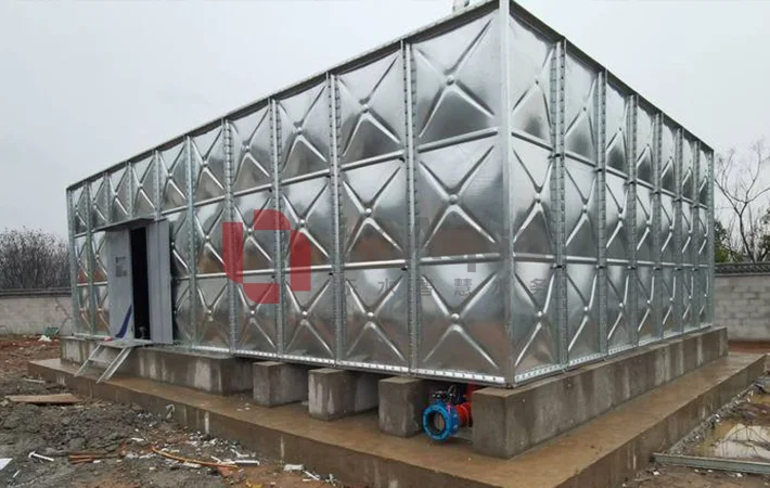
Step 4: Coordinate pipework, drainage and pump interfaces
Foundation work and pipework cannot be reviewed separately. Outlet and suction connections may need a defined elevation, a valve chamber, an access route or an independent support arrangement.
The water tank connection specification guide explains the project information needed for inlet, outlet, overflow, drain and vent interfaces. The same connection schedule should be used by the civil, structural, mechanical and tank installation teams.
Pipework should not impose unintended loads on tank nozzles or panels. Where a pump set is connected to the tank, the suction arrangement, valve access and equipment foundation should be reviewed together. LeAqua’s integrated pump station guide can be used as a reference when the project combines storage, pumps and controls.
Step 5: Review the site before the tank arrives
The foundation may be structurally adequate and still be difficult to use if the site has not been prepared for sectional assembly.
Confirm the following before shipment or mobilization:
- Delivery route from the unloading point to the installation area
- Door, corridor, staircase and lifting clearances
- Space for panel staging and protective packaging
- Temporary storage conditions for panels, seals and accessories
- Working space around the tank for bolting, inspection and cleaning
- Safe access to roof, manholes, valves and instruments
- Drainage route for testing, flushing and future maintenance
The sectional water tank shipping and site-readiness guide covers packing, package handling and site information that should be confirmed before delivery.
Common foundation mistakes
Designing from empty-tank weight only
The empty tank is only one part of the design load. The supporting structure must be checked for the stored water and the other project-specific load cases.
Using nominal dimensions as the entire foundation footprint
The foundation plan should account for the actual tank envelope, support arrangement, connection zones, access and drainage. Nominal capacity alone does not define the base geometry.
Leaving the foundation level until installation
Panel assembly and pipework coordination become more difficult when the base elevation has not been surveyed and accepted before delivery.
Supporting connected pipework from the tank
Pipework, valves and pump equipment may need their own supports. The connection schedule should define where external loads are carried so the tank is not used as an unintended structural support.
Treating a supplier drawing as a complete local structural design
A tank drawing provides the equipment interface and design inputs. Soil conditions, building structure, seismic category, local codes and construction responsibilities still need review by the project’s responsible engineer.
What should be included in the foundation submittal?
Before production, the buyer should request a coordinated package that includes:
- Tank general arrangement and foundation interface drawing
- Nominal and effective capacity definitions
- Tank dimensions, support layout and connection elevations
- Design load basis and support reactions, where applicable
- Anchor, restraint or seismic interface details when required
- Drain, overflow and discharge arrangement
- Access, maintenance and assembly clearances
- Required foundation tolerances and inspection points
- Division of responsibility between tank supplier, civil contractor and installer
These documents should be reviewed with the same project reference and revision status. A foundation drawing that uses an earlier tank layout can create costly changes after fabrication.
How LeAqua supports foundation coordination
LeAqua can review the tank capacity, footprint, panel arrangement, connection elevations and site constraints as part of a project quotation or technical proposal. This helps the buyer identify missing civil and mechanical inputs before the tank is released for production.
LeAqua’s role: LeAqua coordinates tank interface information for the quotation and technical submittal. The project’s responsible civil and structural designers use that information to approve the foundation for the actual site.
The final foundation and supporting structure remain project-specific. They should be approved by the responsible local structural engineer using the supplier’s current drawings, the site information and the applicable requirements.
Frequently asked questions
Does every sectional water tank need a concrete foundation?
No. Many ground-level installations use reinforced concrete, but a raised plinth, steel support frame or another engineered arrangement may be appropriate for a particular site. The support solution must match the tank design and the supporting structure.
Can an existing concrete slab support a sectional water tank?
Possibly, but its capacity, condition, reinforcement, levelness and load path must be checked. The review should use the proposed tank’s filled condition and support reactions rather than relying on the slab’s original purpose.
Should water tank pipework be supported independently?
External pipework and valves should be coordinated so that their weight, movement and operating forces do not impose unintended loads on the tank. The project drawings should define the support and restraint arrangement.
What information should be sent to the tank supplier?
Send the required capacity, tank application, available footprint, foundation elevation, site access, connection schedule, water levels, soil or structural information and any local design requirements. The water tank RFQ checklist helps organize these inputs.
Conclusion
Good sectional water tank foundation design connects four items before installation: the filled-tank load, the actual support arrangement, the connection and drainage layout, and the conditions at the installation site. Coordinating these items early reduces the risk of level problems, unsupported pipework, access restrictions and late civil changes.
For a project review, send LeAqua the required capacity, proposed tank location, foundation information, connection layout and site constraints. The engineering team can then identify the tank interface data that the project’s structural and civil designers need.