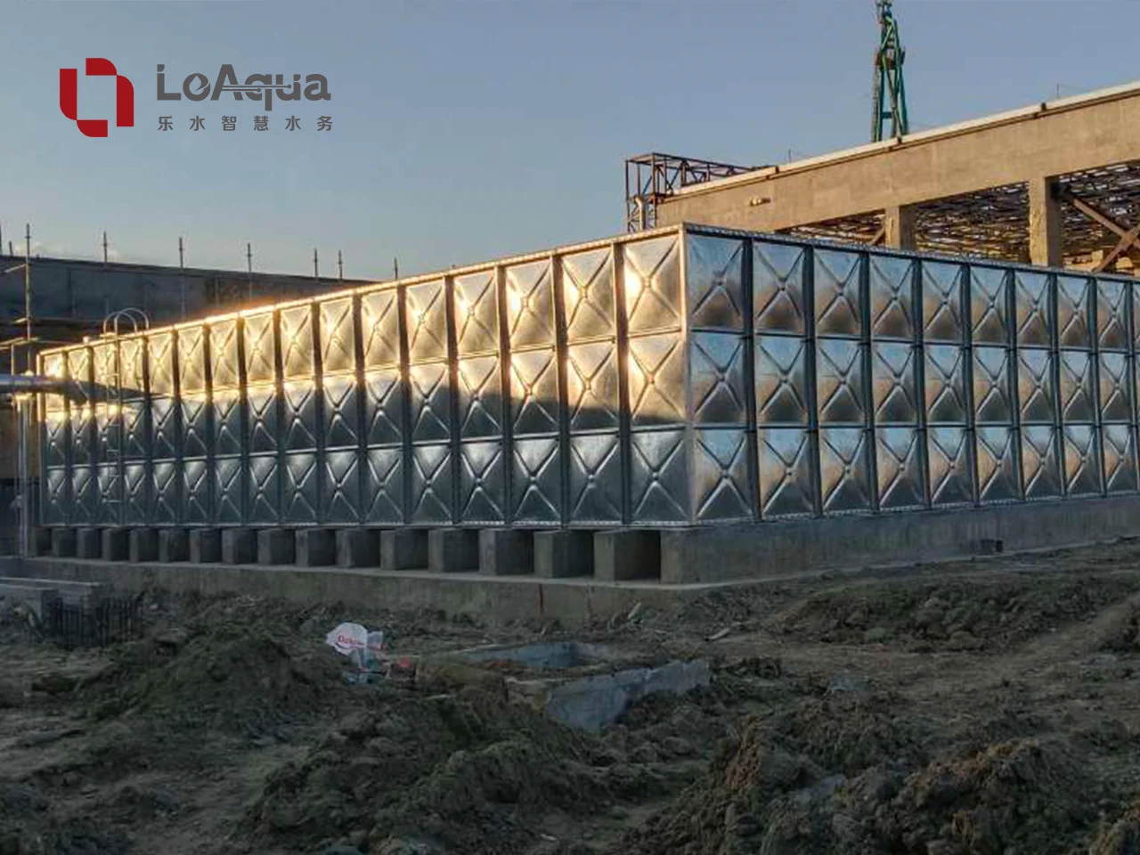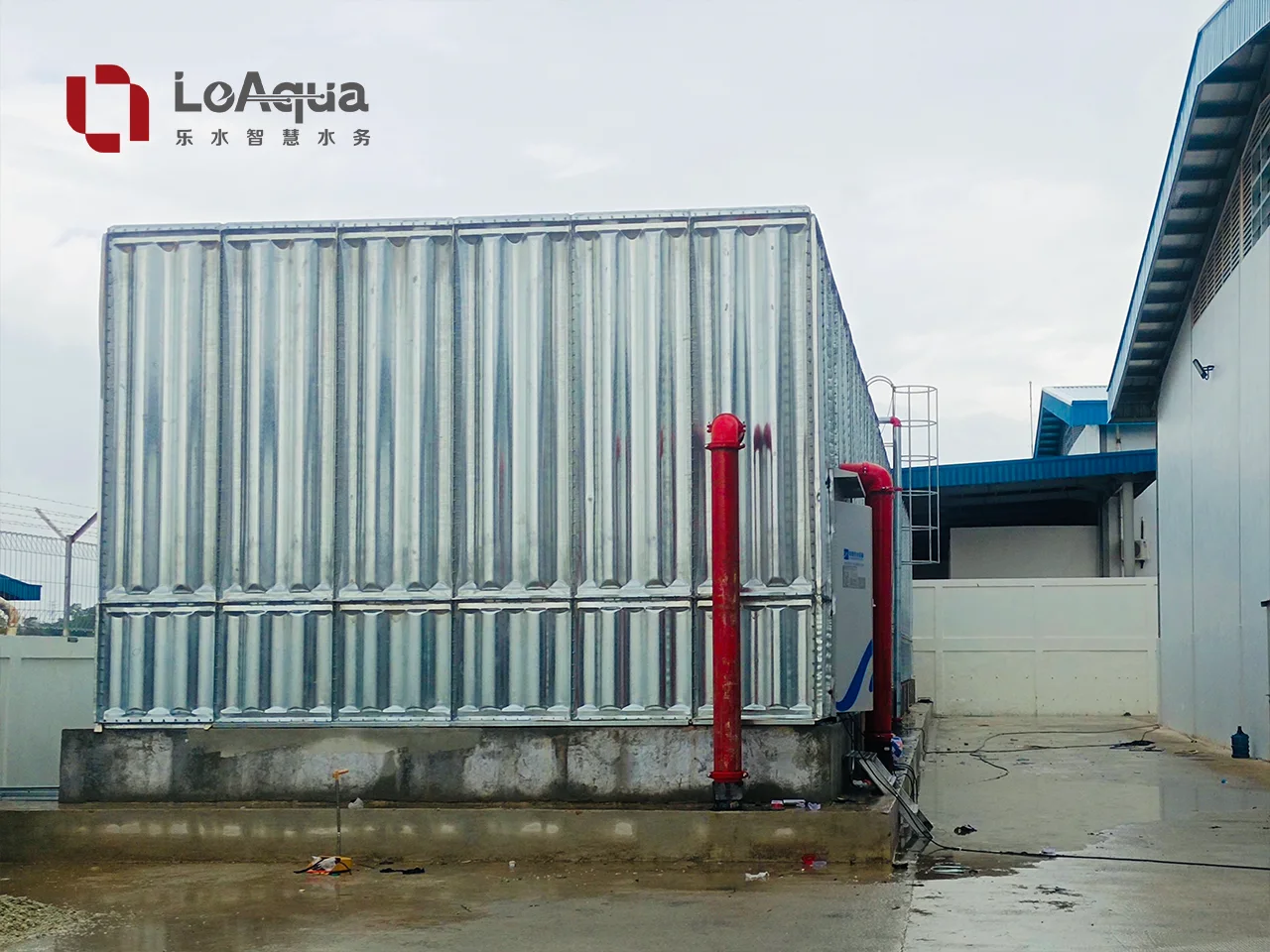
Water tank roof installation requires more than checking whether the roof has enough area. The project must coordinate the tank’s empty and operating loads, support points, waterproofing, access route, pipework, overflow discharge, maintenance clearance and any seismic or wind restraints. The roof structure engineer should verify the supporting slab or steelwork before the tank is ordered.
Quick answer: A roof-mounted water tank should be located over a verified load path, with its full and empty reactions, support details, access requirements, pipe movement and drainage shown on coordinated drawings. The roof membrane and building structure should not be treated as part of a standard tank base detail.
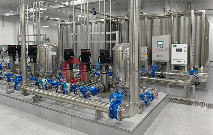
Why rooftop tanks need early coordination
Ground-level tanks usually transfer their weight to a dedicated slab or foundation. A roof-mounted tank transfers load into a building that already has its own dead load, live load, wind load, equipment, waterproofing and service penetrations. The available roof area therefore does not tell you whether the installation is suitable.
Before requesting a final quotation, collect:
- roof plan and structural framing information;
- slab or steel support arrangement;
- allowable construction and operating loads from the structural engineer;
- tank dimensions, full operating level and empty weight;
- access path for panels, roof sections, tools and replacement parts;
- inlet, outlet, overflow, drain, vent and pump connections;
- waterproofing, insulation, finishes and drainage layout;
- wind, seismic and local code criteria where applicable;
- required inspection, cleaning and equipment replacement method.
The roof support may be a concrete plinth, steel grillage, beams, a service platform or another engineered arrangement. Each option changes the reaction points and the construction sequence.
Separate the load cases
A roof-mounted water tank should not be represented by one “tank weight” number. At minimum, the design team usually needs to distinguish:
- empty tank and permanent accessories;
- operating tank with the specified water level;
- maximum water condition or overflow level;
- maintenance condition with people, tools or temporary equipment;
- wind, seismic and pipework actions where they apply;
- installation-stage loads from panels, lifting equipment or stored materials.
The operating load is often the governing gravity condition, while empty or partially filled conditions can matter for wind, seismic response and temporary stability. The supplier should state which tank, roof, ladder, platform, pipe and pump items are included in each reaction.
Design point: Ask for support reactions at the actual support points, not only total weight. A roof engineer needs the location and distribution of vertical, lateral, uplift and overturning actions to check the slab, beams, anchors and local reinforcement.
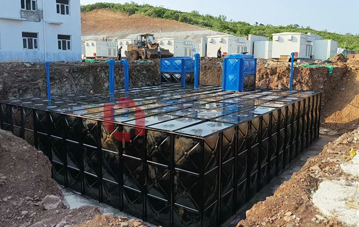
Support arrangement and load path
The support detail should create a direct and inspectable load path from the tank base into the roof structure. Avoid relying on a thin screed, insulation layer or waterproofing membrane to distribute concentrated reactions unless the structural design specifically allows it.
Check:
- base plates, rails, legs or plinth dimensions;
- support spacing and local bearing pressure;
- concrete or steel capacity at every reaction point;
- anchor type, edge distance and installation access;
- differential deflection between supports;
- vibration from pumps or nearby mechanical equipment;
- movement joints and separation between building zones;
- corrosion protection where steelwork passes through or near the roof build-up.
The sectional water tank foundation guide explains the base and load information that should be requested for a tank. On a roof, add the existing building structure, waterproofing and construction-stage constraints to the same review.
Waterproofing and drainage interfaces
A tank support can create punctures, trapped water and difficult-to-inspect areas. The support detail should show how the waterproofing is protected, terminated and repaired around plinths, anchor plates, pipe sleeves and drainage channels.
Do not allow the tank overflow or drain to discharge onto the roof membrane or into an inaccessible corner. Route the discharge to a designed drain or safe outlet that can handle the flow and remain visible during testing. Keep the outlet away from electrical equipment, façade openings and pedestrian routes.
Where the tank sits over an occupied area, a leak detection or secondary drainage strategy may be justified. That is a building-services decision, but the tank supplier should provide drain, overflow and access locations early enough for the architect and MEP engineer to coordinate them.
The water tank connections guide can help organize the connection schedule. For a roof installation, add pipe support, movement, waterproofing penetration and discharge-route columns to that schedule.
Access is part of the design, not an afterthought
The tank must be reachable for inspection, cleaning, sensor replacement and leak investigation. A ladder that reaches the roof is not necessarily a complete maintenance route. Review:
- safe approach from the building stair or service area;
- clear route around the tank and between support members;
- roof hatch and tank manhole position;
- working space to remove covers, filters, sensors and valves;
- lifting path for panels, motors and replacement components;
- guardrails, gates, toe boards or other edge protection;
- lighting, drainage and slip resistance;
- restrictions on access during rain, wind, heat or other site conditions.
US EPA inspection checklists treat hatch condition, sealing, locking and rooftop access as separate inspection items. OSHA rules for US workplaces also require safe access and walking-working surfaces; projects in other countries should follow their own occupational-safety requirements.
The water tank handover documents article explains why access, inspection records and as-built information should be included in the closeout package. Those records are more useful when the access route and equipment clearances were fixed on the approved drawings.
Hatches, vents and roof-mounted accessories
Roof-mounted tanks often have more than one opening: access hatch, vent, overflow, level sensor, cable entry, dosing connection or inspection point. Each penetration needs a watertight detail and enough clearance for inspection.
For potable-water applications, the hatch should be raised, sealed and protected from rain and contamination according to the applicable water authority requirements. For fire or process water, the sanitary criteria may be different, but watertight covers and maintainable openings still matter.
The vent should not be hidden below a roof drain or placed where maintenance staff will step on it. The roof hatch should not conflict with internal tie members, partitions, ladders or lifting equipment. If the tank uses a removable roof panel, show its lifting direction and storage location during maintenance.
Pipework, pumps and building movement
Pipework connected to a roof tank may be fixed to a different structural zone from the tank. Building movement, thermal expansion, seismic displacement and pump vibration can transfer force into tank nozzles if the supports and flexible connections are not coordinated.
Confirm:
- pipe anchors and guides relative to the tank;
- flexible connections and their movement purpose;
- nozzle loads or the method used to check them;
- pump suction alignment and support;
- thermal insulation and waterproofing at sleeves;
- overflow and drain lines that remain visible and accessible;
- isolation valves located where operators can reach them.
If a pump skid is on the roof, keep its operating vibration and maintenance loads separate from the tank support calculation. The pump suction article on inlet arrangement, NPSH and cavitation checks covers hydraulic coordination; the roof design must add structural and movement coordination.
Wind and seismic restraint
An empty or partially filled rooftop tank can have a different stability condition from a full tank. Wind uplift, sliding and overturning should be checked with the tank supports and anchors. Seismic projects also need to review sloshing, anchor forces, support reactions and movement between the tank and building.
The final criteria depend on the site, tank geometry, building structure and applicable code. A supplier should not label a generic roof base “wind-proof” or “seismic compliant” without identifying the design assumptions. Until the project criteria are confirmed, keep the tank reactions and restraint assumptions open in the quotation.
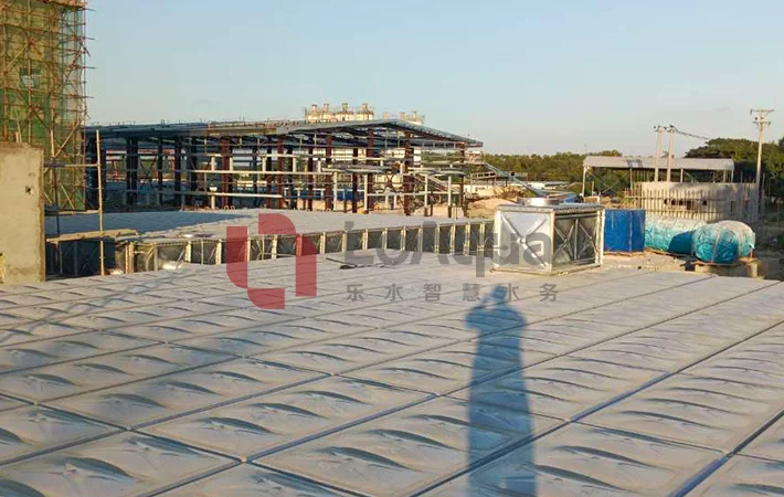
Supplier information to request
| Information | Why the roof team needs it |
|---|---|
| Tank dimensions and water levels | Defines footprint, clearance and operating load |
| Empty and operating weights | Separates permanent and water-induced actions |
| Support reactions | Allows slab, beam, plinth and anchor checks |
| Base or rail detail | Coordinates load transfer and waterproofing |
| Anchor assumptions | Identifies bolt, plate, edge-distance and embedment needs |
| Nozzle schedule | Coordinates pipe movement, sleeves and access |
| Roof and hatch details | Protects water quality and maintenance access |
| Overflow and drain route | Prevents uncontrolled discharge on the roof |
| Accessory weights | Includes ladders, sensors, cabinets, pumps and platforms |
| Installation sequence | Checks temporary storage and lifting loads |
Common mistakes
Putting the tank where the roof looks strongest
The visible roof surface may not correspond to beams or columns below. Confirm the structural grid and load path before fixing the footprint.
Designing only the final operating load
Panel storage, lifting equipment, temporary water, maintenance tools and partially filled conditions can create different reactions during construction and operation.
Blocking the maintenance route
A compact footprint may save roof area but leave no room to remove a hatch cover, service a valve or replace a sensor. Draw the maintenance envelope, not just the tank outline.
Discharging water onto the membrane
An overflow that is acceptable at ground level can damage a roof build-up or flood an occupied area. Route it to a visible, designed discharge point.
Allowing rigid pipework to restrain the tank
Pipe anchors and supports can add hidden lateral loads. Confirm movement and nozzle-load assumptions before the pipework is installed.
How LeAqua can support rooftop tank coordination
LeAqua can use the requested capacity, dimensions, support condition, connection schedule and access constraints to prepare a project-specific tank arrangement and technical data package. The supplier’s contribution is the tank geometry, support and connection information; the building structural engineer remains responsible for the roof structure, anchors, waterproofing and final code compliance.
For the quotation, send the roof plan, support information, operating levels, access route, required documents and pipework assumptions together. This makes exclusions visible and reduces redesign after the tank footprint has been approved.
Frequently asked questions
Can any sectional water tank be installed on a roof?
No. Suitability depends on the building’s structural capacity, support arrangement, access route, waterproofing and project loads. A tank that works at grade may require a different base, reinforcement or capacity when installed on a roof.
Does the roof need a separate plinth?
Often it does, but the solution depends on the roof structure and tank support system. A structural engineer should decide whether a concrete plinth, steel grillage, beam-supported frame or another detail is appropriate.
How much maintenance clearance is required around a roof tank?
There is no single universal clearance. Leave enough space for the actual hatch, valves, instruments, filters, flexible connectors, lifting path and safe worker access shown in the maintenance plan. Local safety and building requirements also apply.
Who designs the roof anchors?
The contract should state the responsibility. The tank supplier can provide base dimensions, reactions and anchor assumptions; the project structural engineer normally verifies the roof structure, concrete or steel support and final anchor design.
Reference material
- US EPA Finished Water Storage Tank Inspection/Cleaning Checklist
- US EPA Sanitary Survey Field Reference
- WBDG UFGS 33 16 15 Water Storage Steel Tanks
- WBDG VA 22 12 16 Facility Elevated, Potable-Water Storage Tanks
- WBDG UFGS 01 33 00 Submittal Procedures
- FEMA E-74: Reducing the Risks of Nonstructural Earthquake Damage
Conclusion
Water tank roof installation is a structural and maintenance coordination problem as much as a tank-selection problem. Confirm the full load path, separate the load cases, protect the roof membrane, coordinate every penetration and pipe movement, and draw the access route before fabrication. A clear roof installation package gives the building engineer, tank supplier and site team the same assumptions to work from.