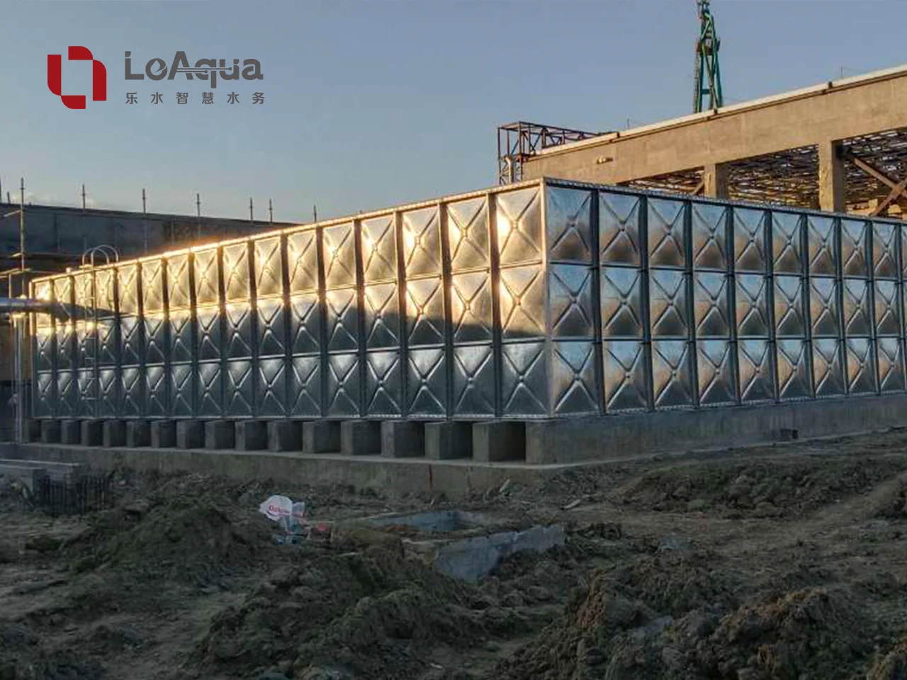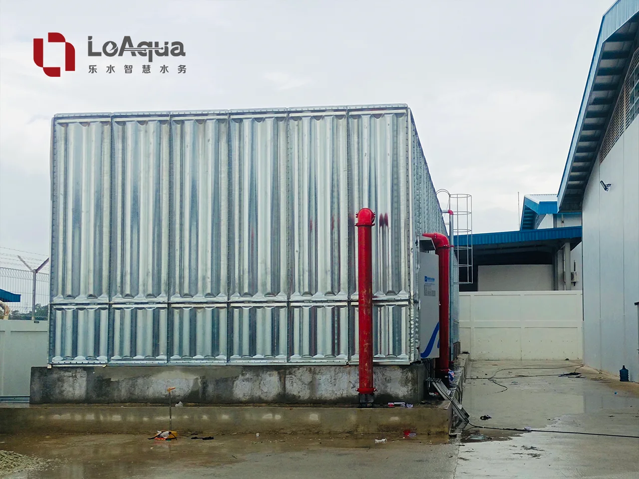
Seismic design for a sectional water tank is not solved by simply making the panels thicker. The design must coordinate the stored-water mass, liquid sloshing, tank walls, roof and supports, foundation, anchors, connected pipework, and any equipment mounted on or beside the tank. The final seismic loads and detailing should be checked by the project structural engineer against the code and site criteria that apply to the project.
Quick answer: A seismic sectional water tank needs a coordinated design for overturning, sliding, sloshing, panel and support forces, foundation anchorage, flexible pipe connections, and restraint of accessories. Ask the supplier for tank reactions, anchor information, connection details and seismic design inputs before the quotation is finalized.
This guide explains the coordination points that matter during design, procurement and installation. It is intended for project owners, MEP engineers, EPC contractors and buyers comparing sectional tank proposals.
Why seismic design should begin before the quotation
The tank is often ordered from a general capacity and footprint. That approach can work for a straightforward site, but it leaves important seismic questions unanswered. A tank that fits the required volume may still need a different support arrangement, base connection, nozzle layout or restraint strategy for a seismic location.
The supplier normally needs project information such as:
- site location and the applicable structural or seismic code;
- tank duty, operating water level and required effective capacity;
- tank length, width, height and compartment arrangement;
- whether the tank is installed indoors, outdoors, at grade, on a roof or on a raised structure;
- foundation type, concrete strength and available anchor zones;
- inlet, outlet, overflow, drain and make-up pipe locations;
- pump suction arrangement and the required pipe flexibility;
- access ladders, platforms, level instruments, control cabinets and other attached items.
The project engineer then uses the site criteria to establish the design actions. A supplier can provide the tank geometry, mass information, connection layout and support reactions, but should not invent a seismic category or guarantee a performance level without the project data and a defined design responsibility.
What changes in a seismic condition?
When the ground moves, the tank and its stored water do not respond as one perfectly rigid block. Two effects are especially important: the part of the water that moves with the tank and the part that moves relative to the tank through sloshing. Earthquake-resistant design guidance commonly treats these as different components because they create different forces and periods of response.
1. Impulsive water response
The impulsive component moves with the tank wall and contributes to the forces transferred into the panels, supports, anchors and foundation. It affects the overturning and sliding checks, as well as the demand on the tank-to-support connection.
2. Convective response and sloshing
The convective component represents the water surface moving relative to the tank. Sloshing can create additional freeboard requirements, impact near the roof or cover, and fluctuating loads at walls, partitions and attached fittings. The water level used for the design therefore matters; a tank designed only around the nominal volume may not have the same freeboard or operating condition as the final project arrangement.
Design point: Sloshing is not only a tank-wall issue. It can affect freeboard, roof clearances, level sensors, internal partitions, access openings and the loads transferred through connected pipework. The operating level and compartment arrangement should be confirmed before the tank layout is frozen.
3. Sliding, overturning and local force paths
The seismic load path should be traceable from the water and tank panels through the supports, base plates or rails, anchors, concrete and supporting structure. A global stability check does not replace checks of local bolts, brackets, panel joints, stiffeners, roof framing, nozzle reinforcement or the supporting slab.
Tank structure and support checks
For a sectional tank, seismic review should cover more than the material grade shown on the quotation. The following interfaces deserve a clear design note or drawing reference.
Panel joints and stiffening
Panel thickness, rib arrangement, flange geometry, bolts, gaskets and internal or external stiffeners work together. Cyclic movement can increase demand at joints and support lines, especially where a tank wall changes direction or where a partition interrupts the load path. The supplier should identify the selected panel system and show how loads are transferred between panels and supports.
The project team should also confirm whether the tank has a roof frame, internal tie members, partitions or other components that change the effective load path. Do not assume that a standard panel schedule is suitable for every height, compartment arrangement or support condition.
Supports, rails and legs
The support system must be compatible with both the tank design and the foundation. Check bearing areas, rail or leg spacing, local concrete pressure, bolt access, corrosion protection and the possibility of differential movement. A raised tank or roof-mounted tank usually needs a separate review of the supporting steel or concrete structure; the tank supplier’s reactions are inputs to that review, not a replacement for it.
Roof and access components
Roof panels, covers, ladders, handrails and walkways can experience relative movement. Their connections should not be treated as decorative details. Confirm clearances around manholes, vents, overflow arrangements, level sensors and removable panels, particularly where the tank may be partially full during operation or inspection.
Anchoring and foundation coordination
Anchoring is one of the most common gaps between a tank quotation and a construction-ready design. “Anchor bolts included” is not enough information for a seismic project. The design team needs to know what is being anchored, where the forces enter the concrete, and which party designs the concrete and reinforcement.
The tank and structural drawings should coordinate:
- tank base dimensions and support points;
- anchor type, diameter, spacing, embedment and edge distances;
- tension, shear and combined actions at the anchors;
- base plate, rail or bracket dimensions;
- concrete strength, reinforcement and local thickening requirements;
- construction tolerances and access for drilling, setting or tightening;
- corrosion protection and inspection requirements;
- the interface with waterproofing, roof slabs or raised steelwork.
The concrete slab may be adequate for gravity load but inadequate for overturning or anchor tension. Conversely, adding anchors without checking edge distance, reinforcement congestion or concrete breakout can create a detail that is difficult to build and difficult to approve. The final anchor and foundation design should be signed off by the responsible structural engineer.
For an existing slab, request as-built information or arrange a site survey before selecting the tank support arrangement. Record slab thickness, reinforcement, joints, openings, drains, waterproofing and nearby services. If the proposed tank crosses a movement joint or sits over a suspended slab, the project team should address that condition explicitly rather than relying on a standard base detail.
The LeAqua article on sectional water tank foundation requirements provides a useful starting checklist for base level, load information and site coordination. A seismic project should add the anchor and lateral-load information described above.
Pipework coordination: the tank must be allowed to move
Rigidly connecting a tank to fixed building pipework can transfer unwanted forces into nozzles, panels or supports. In a seismic event, the tank, foundation, pump set and building structure may move differently. Pipework therefore needs its own movement and restraint review.
Flexible connections are not a universal substitute
Flexible connectors, expansion joints or flexible couplings can reduce the transfer of displacement, but they must be selected for the actual pressure, temperature, movement, vacuum and service conditions. A short rubber connector that is suitable for vibration control may not provide the required seismic displacement or axial restraint. It also may not be appropriate on a pump suction line if it creates poor alignment or an unacceptable flow condition.
The connection schedule should state the intended function of each flexible element: vibration isolation, thermal movement, settlement, seismic displacement, or a combination. The adjacent pipe guides, anchors and supports must be designed consistently; otherwise the flexible component may simply move the load to the next nozzle.
Nozzle loads and clearances
Confirm inlet, outlet, overflow, drain and vent locations early. The tank connection article on water tank inlet, outlet, overflow, drain and vent specification can be used to organize the basic connection data, but a seismic project should add:
- expected relative movement between the tank and fixed pipework;
- pipe anchor and guide locations;
- allowable nozzle loads or the method used to verify them;
- clearance to walls, beams, cable trays and other services;
- access for inspection and replacement of flexible components;
- drain and overflow routing that will not impose a restraint or trip hazard.
Pump suction deserves particular care. The water tank pump suction design guide explains why inlet geometry, submergence and air entry matter. For a seismic installation, the suction line also needs coordinated supports and a flexible interface so that movement does not damage the nozzle or disturb pump alignment.
Restraint of accessories and controls
The tank shell may remain stable while an attached accessory becomes the weak point. Review items such as:
- level switches, radar or ultrasonic sensors and their brackets;
- external control cabinets, junction boxes and cable trays;
- pump skids, manifolds and small-bore connections;
- ladders, platforms, handrails and access covers;
- roof vents, overflow screens and removable panels;
- internal partitions, anti-vortex devices or other submerged components.
Each item needs a practical restraint and maintenance detail. A bracket should not rely on a thin panel flange if the accessory has meaningful mass or projects far from the wall. Cable and small-bore pipe connections should have enough slack or flexible sections to accommodate the movement assumed in the design.
What the supplier should provide
Before approving a sectional water tank proposal, request a coordinated submittal package. It does not need to contain the entire building seismic calculation, but it should give the project engineer enough information to complete the interface design.
| Submittal item | Why it matters | What to confirm |
|---|---|---|
| General arrangement drawing | Defines the tank geometry and interfaces | Overall dimensions, water levels, compartments, roof and access |
| Panel and support schedule | Shows the selected construction system | Panel type, ribs, joints, supports and material specification |
| Operating and empty weights | Provides mass inputs | Tank, roof, fittings, pumps and operating water condition |
| Support reactions | Transfers actions to the structure | Vertical, lateral, uplift and overturning reactions, with load cases identified |
| Anchor layout or base detail | Coordinates the concrete interface | Locations, plate or rail sizes, bolt assumptions and tolerances |
| Nozzle and connection schedule | Controls pipework coordination | Size, elevation, orientation, flange standard and any load limitation |
| Flexible connection requirements | Prevents rigid load transfer | Movement purpose, location, pressure rating and adjacent restraint |
| Accessory restraint details | Protects instruments and equipment | Ladders, sensors, cabinets, platforms and roof items |
| Inspection and test records | Supports handover and traceability | Joint checks, leak testing, bolt or weld records and approved drawings |
If a supplier cannot provide final seismic reactions before the quotation, the quotation should state the assumptions and identify what will be issued after the project design inputs are confirmed. This is more useful than presenting an unexplained “seismic compliant” statement.
Information to include in an RFQ
Buyers can reduce revisions by placing the seismic information in the first request for quotation. Include the project country and city, applicable code, design engineer’s criteria, tank location, support condition, operating levels, connection schedule, pipe flexibility assumptions and any required review or approval process.
The water tank RFQ checklist can be expanded with these questions:
- Is the tank at grade, on a roof, on a steel frame or inside a plant room?
- Is the tank connected to a building that may move differently from the foundation?
- What are the full and minimum operating water levels?
- Are there partitions or separate compartments?
- Which party designs the anchors, concrete reinforcement and supporting steel?
- Are flexible connectors required at the inlet, outlet, overflow, drain or pump suction?
- What drawings, calculations and inspection records are required for approval?
- Does the local authority require a licensed engineer’s review or a specific standard?
Clear answers to these questions help suppliers compare the same scope and help buyers identify exclusions before the purchase order is issued.
Common mistakes to avoid
Mistake 1: Treating “earthquake resistant” as a product category
An earthquake-resistant water tank is not defined by a marketing label alone. Performance depends on the tank geometry, water level, support system, anchors, foundation, pipework and project criteria. Ask for the assumptions and design interfaces behind the claim.
Mistake 2: Designing only the tank shell
The shell may be checked while the anchor group, support steel, nozzle or access platform is left to site improvisation. The complete load path needs to be reviewed before fabrication.
Mistake 3: Using a standard rigid pipe connection
A standard detail may be acceptable for a fixed, non-seismic installation but transfer excessive displacement or force in a seismic condition. Confirm movement, pipe restraint and nozzle loads together.
Mistake 4: Ignoring partial-fill operation
The tank may be full during a design check but operate at a lower level for much of its life. Sloshing, freeboard and equipment restraint should be considered for the operating conditions specified by the project, not only the maximum capacity.
Mistake 5: Leaving responsibility unclear
The purchase order should distinguish the supplier’s tank design and interface data from the project engineer’s responsibility for the building, foundation, anchors, pipe supports and final code compliance. A responsibility matrix prevents gaps at the approval stage.
How LeAqua can support the coordination process
For a project-specific proposal, LeAqua can use the requested capacity, material, dimensions, connection arrangement, foundation information and pump requirements to prepare a tank configuration and technical submission. The useful deliverable is not just a tank price; it is a coordinated set of drawings, schedules and interface assumptions that the project team can review.
The seismic design itself remains project-dependent. The responsible structural engineer should confirm the applicable code, design actions, support structure, anchors and concrete details. LeAqua’s role is to provide accurate tank geometry, connection information, equipment data and manufacturing or inspection documents needed for that review.
Frequently asked questions
Does a sectional water tank need seismic anchoring?
It may need anchoring or another engineered restraint system when the project analysis shows a risk of sliding, uplift or overturning. The requirement depends on the tank geometry, water level, support condition, site criteria and applicable code. Do not select anchor details from capacity alone.
How does sloshing affect a water tank design?
Sloshing can change freeboard and create moving-water forces at the walls, roof, partitions and attached fittings. The operating level and compartment arrangement should be included in the design inputs, and clearances for sensors, covers and pipe connections should be checked.
Should flexible connectors be used on every tank nozzle?
No. A flexible connector should be selected for a defined movement and service purpose, then coordinated with pipe anchors, guides, pressure, vacuum and pump requirements. An unsuitable connector can create alignment, leakage or suction problems.
Can a tank supplier certify the complete seismic installation?
Usually, the supplier can provide tank-specific drawings, reactions, connection details and product documentation. The final seismic design of the foundation, supporting structure, anchors and building-connected pipework normally belongs to the project structural or MEP design team under the applicable local requirements. The contract should state the exact scope.
Reference material
The following public sources provide background for seismic design coordination. They do not replace the code, calculations or approvals required for a specific project.
- FEMA E-74: Reducing the Risks of Nonstructural Earthquake Damage — practical guidance on anchorage and restraint of nonstructural components.
- NIST Guide Brief 4A: Example for Determining Anticipated Performance — a water and wastewater infrastructure resilience reference that helps frame performance objectives.
- WBDG UFGS 33 16 15: Water Storage Tanks — a government construction specification reference for water storage tank scope and coordination.
- USGS National Seismic Hazard Model — background on location-specific seismic hazard information.
- USGS Unified Hazard Tool — a current source for location-specific earthquake hazard information where applicable.
Conclusion
Sectional water tank seismic design should be treated as an interface exercise, not a panel-only calculation. Confirm the water levels and sloshing assumptions, trace forces through the supports and anchors, coordinate the foundation, and give connected pipework enough controlled movement. Request these inputs before the quotation is finalized so the tank, structure and installation team are working from the same design basis.
For a project quotation, send the tank duty, site and code information, operating levels, foundation details, connection schedule and required submittals together. That gives the supplier a realistic basis for the tank configuration and gives the project engineer the information needed to complete the seismic review.